4 ct table for pbvi board, Ct table for pbvi board, Table 2 – Liebert Distribution Monitoring LDM User Manual
Page 14
Installation
10
4.4
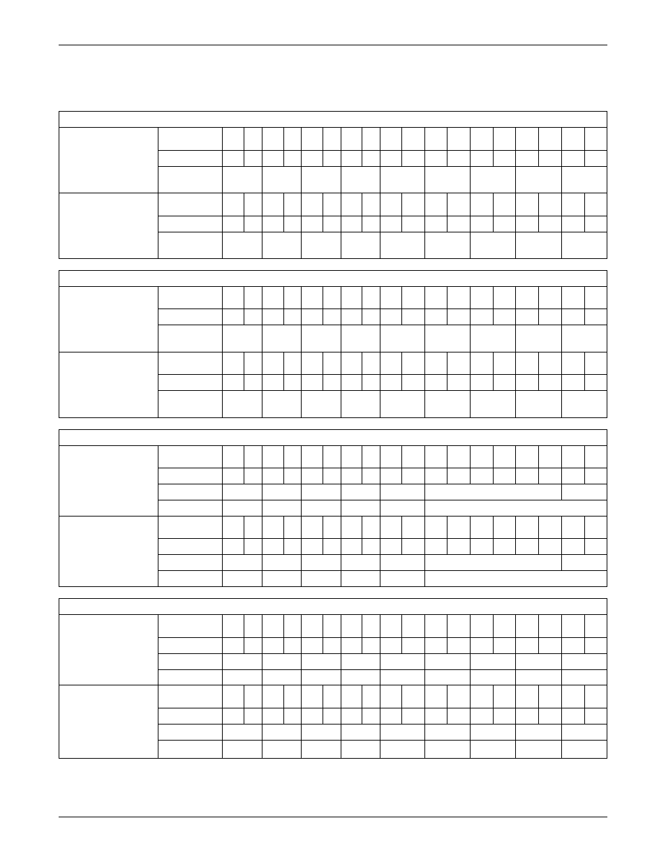
CT Table for PBVI Board
Table 2 shows the configuration of large branch circuit breakers and their CT assignments.
Table 2
Wiring configuration of large branch circuit breakers
Configuration 1: Four Modules
Connector P3 (A)
Pins
▼
1
2
3
4
5
6
7
8
9
10
11
12
13
14
15
16
17
18
Wire Color
W
B
W
B
W
B
W
B
W
B
W
B
W
B
W
B
W
B
CT
CT1
CT2
CT3
CT4
CT5
CT6
CT7
CT8
CT9
or IG
Connector P4 (B)
Pins
▼
1
2
3
4
5
6
7
8
9
10
11
12
13
14
15
16
17
18
Wire Color
W
B
W
B
W
B
W
B
W
B
W
B
W
B
W
B
W
B
CT
CT10
CT11
CT12
CT13
CT14
CT15
CT16
CT17
CT18
or IG
Configuration 2: Two Modules With Large Branch Breaker CTs
Connector P3 (A)
Pins
▼
1
2
3
4
5
6
7
8
9
10
11
12
13
14
15
16
17
18
Wire Color
W
B
W
B
W
B
W
B
W
B
W
B
W
B
W
B
W
B
CT
LB1
LB2
LB3
LB4
LB5
LB6
LB7
LB8
LB9
or IG
Connector P4 (B)
Pins
▼
1
2
3
4
5
6
7
8
9
10
11
12
13
14
15
16
17
18
Wire Color
W
B
W
B
W
B
W
B
W
B
W
B
W
B
W
B
W
B
CT
LB10
LB11
LB12
LB13
LB14
LB15
LB16
LB17
LB18
or IG
Configuration 3: Four Modules With Two 5-Wire Subfeed Breaker CTs
Connector P3 (A)
Pins
▼
1
2
3
4
5
6
7
8
9
10
11
12
13
14
15
16
17
18
Wire Color
W
B
W
B
W
B
W
B
W
B
CT
LB1
LB2
LB3
LB4
LB5
IG
Phase
A1
B1
C1
N1
G1
Connector P4 (B)
Pins
▼
1
2
3
4
5
6
7
8
9
10
11
12
13
14
15
16
17
18
Wire Color
W
B
W
B
W
B
W
B
W
B
CT
LB6
LB7
LB8
LB9
LB10
IG
Phase
A2
B2
C2
N2
G2
Configuration 4: Four Modules With Three 5-Wire Subfeed Breaker CTs
Connector P3 (A)
Pins
▼
1
2
3
4
5
6
7
8
9
10
11
12
13
14
15
16
17
18
Wire Color
W
B
W
B
W
B
W
B
W
B
W
B
W
B
W
B
W
B
CT
LB1
LB2
LB3
LB4
LB5
LB11
LB12
IG
Phase
A1
B1
C1
N1
G1
N3
G3
Connector P4 (B)
Pins
▼
1
2
3
4
5
6
7
8
9
10
11
12
13
14
15
16
17
18
Wire Color
W
B
W
B
W
B
W
B
W
B
W
B
W
B
CT
LB6
LB7
LB8
LB9
LB10
LB11
LB12
LB13
IG
Phase
A2
B2
C2
N2
G2
A3
B3
C3
W = White
B = Black
IG = Isolated Ground CT
LB = Large Branch Breaker CT
A = A Phase CT
B = B Phase CT
C = C Phase CT
N = Neutral CT
G = Ground CT