Installation – Lincoln Electric POWER FEED IM584-D User Manual
Page 18
A-10
INSTALLATION
POWER FEED 10
A-10
SETTING DIP SWITCHES IN THE WIRE
DRIVE
There is one DIP switch bank on the control board of
the wire drive. Itʼs labeled S1 and is located and ori-
ented as shown in Figure A.4.
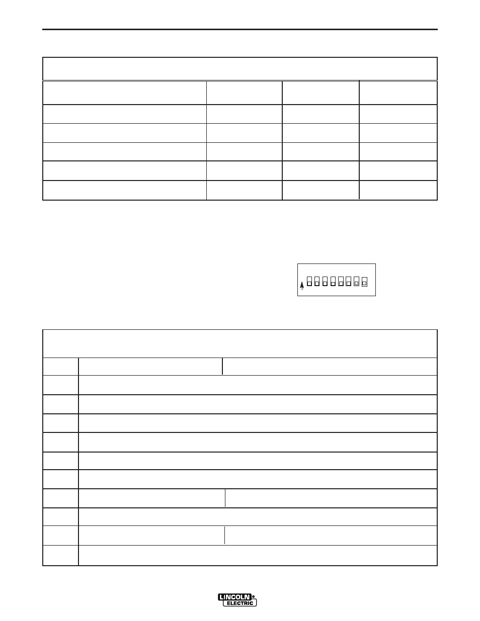
FIGURE A.4
S1 DIP Switch on Wire Drive Control Board (For software version S24029-All & S24467)
Switch
Off
On
1
Network Group ID, MSB (Assigns Wire Drive to a specific group)
2
Network Group ID, LSB (Assigns Wire Drive to a specific group )
3
Network Feed Head ID, MSB (Assigns feed head number to wire drive)
4
Network Feed Head ID (Assigns feed head number to wire drive)
5
Network Feed Head ID, LSB (Assigns feed head number to wire drive)
6
Spare
7
Electrode Sense Polarity = Positive
Electrode Sense Polarity = Negative
Switch position must match polarity of weld cable attached to feed plate.
8
Gear Box Ratio = Low
Gear Box Ratio = High
Switch position must match actual gear box ratio of wire drive.
Note: the factory shipped settings for all of the S1 switches is “OFF”.
S1
ON
1
2
3
4
5
6
7
8
DIP SWITCH 6
DIP SWITCH 7
DIP SWITCH 8
Acceleration 1 (slow)
Off
Off
On
Acceleration 2
Off
On
Off
Acceleration 3
Off
On
On
Acceleration 4
On
Off
Off
Acceleration 5 (fast ) (factory setting)
Off
Off
Off
Setting Wire Drive Acceleration Rate Using
(All software versions)
DIP Switch S1 on the Control Box Motherboard