Lennox Hearth MERIT PLUS MP-36OD User Manual
Page 13
NOTE: DIAGRAMS & ILLUSTRATIONS ARE NOT TO SCALE.
13
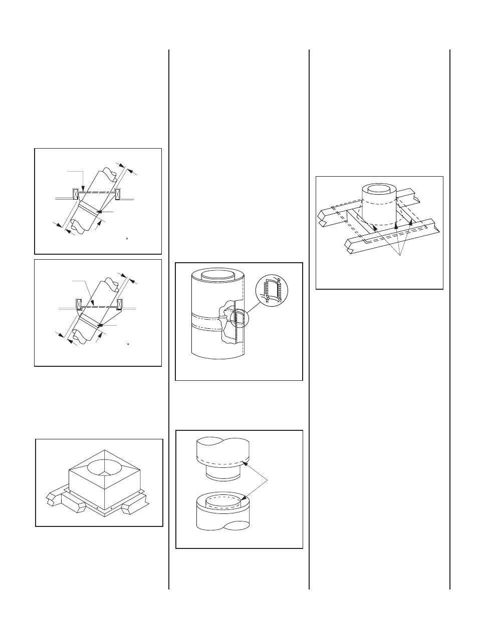
CHIMNEY 30° OFFSET THROUGH
FLOOR OR CEILING
It may be necessary to assemble the chimney
at 30° when passing through the fl oor or ceiling
area. Use the F8FS30 fi restop spacer as shown
in Figures 31 & 32. Support the chimney at fl oor
or ceiling penetration with a FTF8 stabilizer if
distance of chimney below ceiling is 10' or more.
Maintain 1"* minimum air space to combustibles
from chimney sections.
Figure 31
Step 4. Note: Chimney sections are constructed
with a unique locking tab design, which ensures
an immediate, tight assembly between sections.
Plan your chimney requirements carefully before
assembly as chimney is diffi cult to disassemble
after installation. If disassembled, the tabs
might become damaged. Be certain tabs are
properly formed to ensure locking tabs engage
properly.
The Security Chimney's FTF8 chimney system
is a two piece chimney, which snap together
from the fi replace up. Start with the inner fl ue
section with the lanced end up, snap lock it in
to the matching collar on top of the fi replace.
At all subsequent joints, the upper fl ue section
fi ts into the preceding fl ue section. Each piece
snaps together by means of locking tabs (9
locking tabs per joint). Check each piece by
pulling up slightly from the top to ensure proper
engagement before installing the next section.
If the fl ue has been installed correctly, it will not
separate when you test it. Also, the inner fl ue
joint where each section is joined should be
tight and fl at without gaps (Figure 34).
The outer chimney section installs the opposite-
way; the lanced end goes down and each new
section goes OVER the outside of the previous
section installed (Figure 35).
For Canada Only
When installing the chimney system through
an open attic space, the attic shield assembly-
fi restop spacer must be used (Figure 33). This
installation is required only for use in Canada.
Note: For Canadian installations, all chimney
installed outside the building must be con-
structed with galvalume on the outer sections
only (Note: galvalume is galvanized). The ap-
propriate model designations are located in the
F8FS30
Firestop Spacer
FTF8-S4 Stabilizer
1"
*
Min.
Air Space
30 Firestop
And Attic Above
10'
Max.
Attic Space
1"
*
Min.
Air Space
F8FS30
Firestop Spacer
FTF8-S4 Stabilizer
30 Firestop
And Room Above
10'
Max.
Room Above
1"
*
Min.
Air Space
1"
*
Min.
Air Space
Open Attic Space
Locking
Tabs
(Lances)
Figure 32
Figure 34
Figure 35
Figure 33
Note: Assemble one component of chimney at
a time (inner section fi rst, then outer section
last) before proceeding with the next complete
section.
Continue to assemble the chimney up through
framed opening. Assemble just enough to
penetrate the roof fl ashing openings (Figure
36). Always maintain 1"* minimum air space to
insulation and construction materials. Always
check each chimney joint (inner and outer)
to ensure proper engagement. Check vertical
alignment of chimney so that it projects from
the roof in true vertical position.
1"
*
Min. Air Space
To Combustibles
Figure 36
Security's chimney sections do not need to be
screwed together. Additional reinforcement is
not necessary except in certain offset conditions
(refer to Page 16, Figure 47).
Step 5. The height of vertical chimney pipe
supported only by the fi replace must not exceed
30'. Chimney heights above 30' must be sup-
ported by a Model FTF8-S4 stabilizer installed
at 30' intervals.
Note: The Model FTF8-S4 adds 3" net effective
height to the total chimney system.
Install the Model FTF8-S4 stabilizer by fi tting
inner section down into respective section of
proceeding fl ue pipe and locking outer stabilizer
section into place over the outer chimney pipe.
Position for proper clearance through framed
opening and nail straps securely (under tension
in “shear”) into place on framing. Use 8d nails.
Attach successive lengths of chimney pipe
directly to stabilizer using same techniques as
described in Step 4 (see Figure 37).
*Notes:
• 2" clearance to combustibles required in
Canada.