System-board switches and jumpers – Lenovo THINKSERVER RS210 User Manual
Page 119
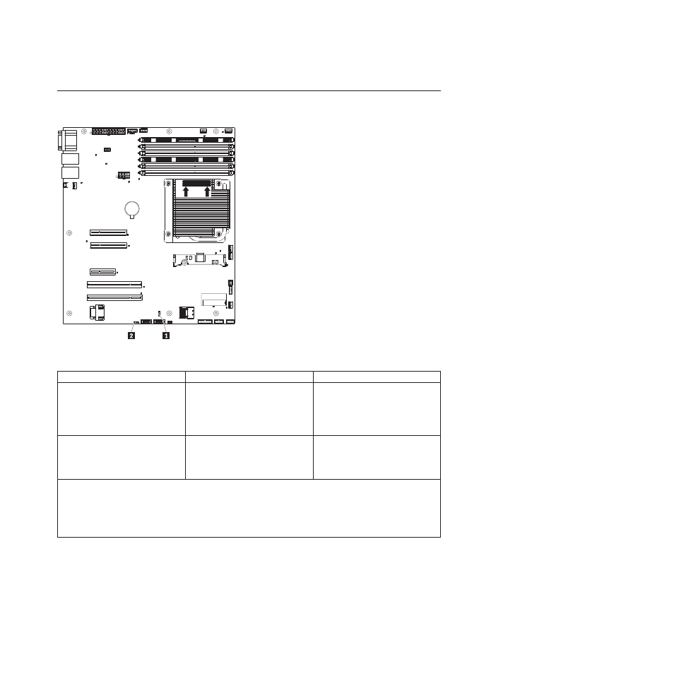
System-board switches and jumpers
The following illustration shows the switches and jumpers on the system board.
Microprocessor
Heatsink
Orientation
DIMMs
DIMMs
The following table describes the jumpers on the system board.
Table 6. System board jumpers
Jumper number
Jumper name
Jumper setting
JP1
Clear CMOS jumper 1
v
Pins 1 and 2: Keep CMOS data
(default).
v
Pins 2 and 3: Clear CMOS data
(including power-on password and
administrator password)
JP6
Boot block jumper 2
v
Pins 1 and 2: Boot from primary
BIOS page (default) .
v
Pins 2 and 3: Boot from backup
BIOS page.
Notes:
1.
If no jumper is present, the server responds as if the pins are set to 1 and 2.
2.
Changing the position of the UEFI boot recovery jumper from pins 1 and 2 to pins 2 and 3 before the server is
turned on alters which flash ROM page is loaded. Do not change the jumper pin position after the server is
turned on. This can cause an unpredictable problem.
Important:
1.
Before you change any switch settings or move any jumpers, turn off the server; then, disconnect all
power cords and external cables. Review the information in “Guidelines for trained service
technicians” on page 115, “Handling static-sensitive devices” on page 117, and “Turning off the
server” on page 113.
2.
Any system-board switch or jumper blocks that are not shown in the illustrations in this document
are reserved.
Chapter 5. Locating Server Controls and connectors
111