Warning – Lennox Hearth Crestline LSBV-3628MN User Manual
Page 9
9
NOTE: DIAGRAMS & ILLUSTRATIONS ARE NOT TO SCALE.
LENNOX HEARTH PRODUCTS • CRESTLINE™ SERIES B-VENT GAS FIREPLACES • 36"/42" LSBV MODELS • INSTALLATION INSTRUCTIONS
All appliances are equipped with a gas flex line
and shutoff valve attached directly to the gas
control valve. To quickly and easily complete
the gas line routing, use the gas flex line kit.
Step 3. Position the Appliance - Slide the
fireplace into prepared framing or position
fireplace in its final position and frame later.
Refer to fireplace drawings and specifications
on Page 7 for framing dimensions and details.
Framing header may be positioned directly on
the fireplace top spacers.
IMPORTANT: UNDER NO CIRCUMSTANCES
CAN THE FIREPLACE TOP SPACERS (refer
to Figure 10) BE REMOVED OR MODIFIED,
NOR MAY YOU NOTCH THE HEADER TO FIT
AROUND OR BE INSTALLED LOWER THAN THE
SPACERS. THE HEADER MAY BE IN DIRECT
CONTACT WITH THE TOP SPACERS BUT MAY
NOT BE SUPPORTED BY THEM.
Fireplace should be secured to side framing
members using the full length 1/2 inch nailing
flanges that are integral to the appliance at each
side. Use 6d nails or equivalent (Figure 10).
WARNING
CONNECTING DIRECTLY TO AN UN-
REGULATED PROPANE (L.P.G). TANK
MAY CAUSE AN ExPLOSION.
An external regulator must be used on all pro-
pane (L.P.G). heaters to reduce the supply tank
pressure to 13" w.c. (maximum). Any copper
tubing used to supply propane (L.P.G). from
the tank must be internally tinned.
IMPORTANT: HOLD GAS VALVE SECURELY TO
PREVENT MOVEMENT WHEN CONNECTING TO
INLET GAS LINE
Figure 11
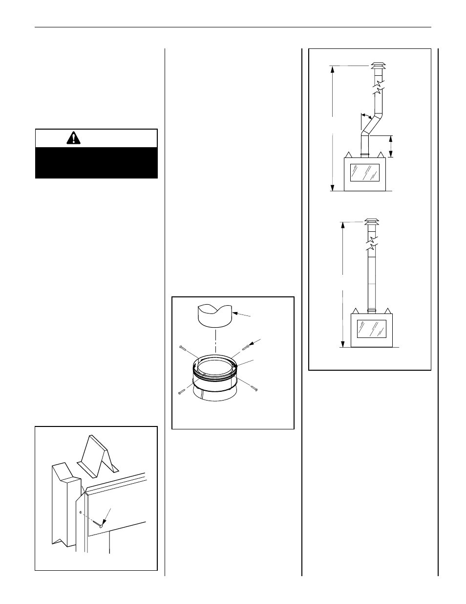
Step 4. Install the Vent System and
Exterior Termination
Slip a 10" (254 mm) B-Vent system over the
appliance collar (Figure 11) and secure with
four sheetmetal screws (# 8 or larger). Minimum
overall height of the vent system and appliance
must be 12' (3.66 m) vertical (no offset) or 17'
(5.18 m) when an offset up to 45 degrees from
the vertical is used. The lower part of the offset
must not begin less than 3' (0.914 m) above the
top of the fireplace (see Figure 12).
Maximum overall height of the vent system and
appliance should not exceed 40 feet (12.19m).
Install the B-vent system in accordance with
the vent manufacturer's instructions.
CAUTION: THIS APPLIANCE CANNOT BE
VENTED HORIZONTALLY.
Note: Refer to the vent manufacturers instal-
lation instructions for variations of venting
techniques. If common venting of several units
is contemplated, it should be discussed with an
architect and the local Building Department.
Note: The nailing flanges and the area directly
behind the nailing tabs are exempt from the
clearances described on the fireplace clear-
ance label.
Figure 10
6d Nail or
Equivalent
10
Type B-Vent
Flue Outlet
Collar
Securing
Screws
12 ft.
Minimum
17 ft.
Minimum
45 degrees
max.
3 ft.
Minimum
to Offset
12 ft.
Minimum
17 ft.
Minimum
45 degrees
max.
3 ft.
Minimum
to Offset
Figure 12