Lennox Hearth Crestline LSBV-3628MN User Manual
Page 14
14
NOTE: DIAGRAMS & ILLUSTRATIONS ARE NOT TO SCALE.
LENNOX HEARTH PRODUCTS • CRESTLINE™ SERIES B-VENT GAS FIREPLACES • 36"/42" LSBV MODELS • INSTALLATION INSTRUCTIONS
MANUALLY-RESET BLOCKED FLUE SAFETY
SWITCH
This appliance is equipped with a manually-reset
blocked flue safety switch. Refer to Figure 26
for its location. If during appliance operation,
the flame goes out (independently of the burner
on/off wall switch), it may be due to the opera-
tion of this safety limit switch. First allow the
appliance to cool. Then reset the safety switch
by pushing the red reset button.
This reset button is located on the back of the
limit switch, between the wire terminals (see
Detail A of Figure 26).
The appliance should then relight and remain
lit. If this does not occur, turn off the appli-
ance and call a qualified service technician.
Figure 26
Detail A
Manual Reset
Limit Switch
Lintel
Extension
Right Side
Refractory Panel
Reset
Button
Wire
Terminals
Figure 28
Replace logs if removed for pilot inspection.
To light the burner; rotate the gas valve control
knob counterclockwise to the “ON” position
(“ON” will be to the right hand side of the valve).
Turn “ON” the remote wall switch.
Electronic Appliance Checkout
To light the burner, turn ‘ON’ the optional remote
wall switch. Ensure the igniter lights the pilot.
The pilot flame should engulf the flame rod as
shown in Figure 28.
Figure 27
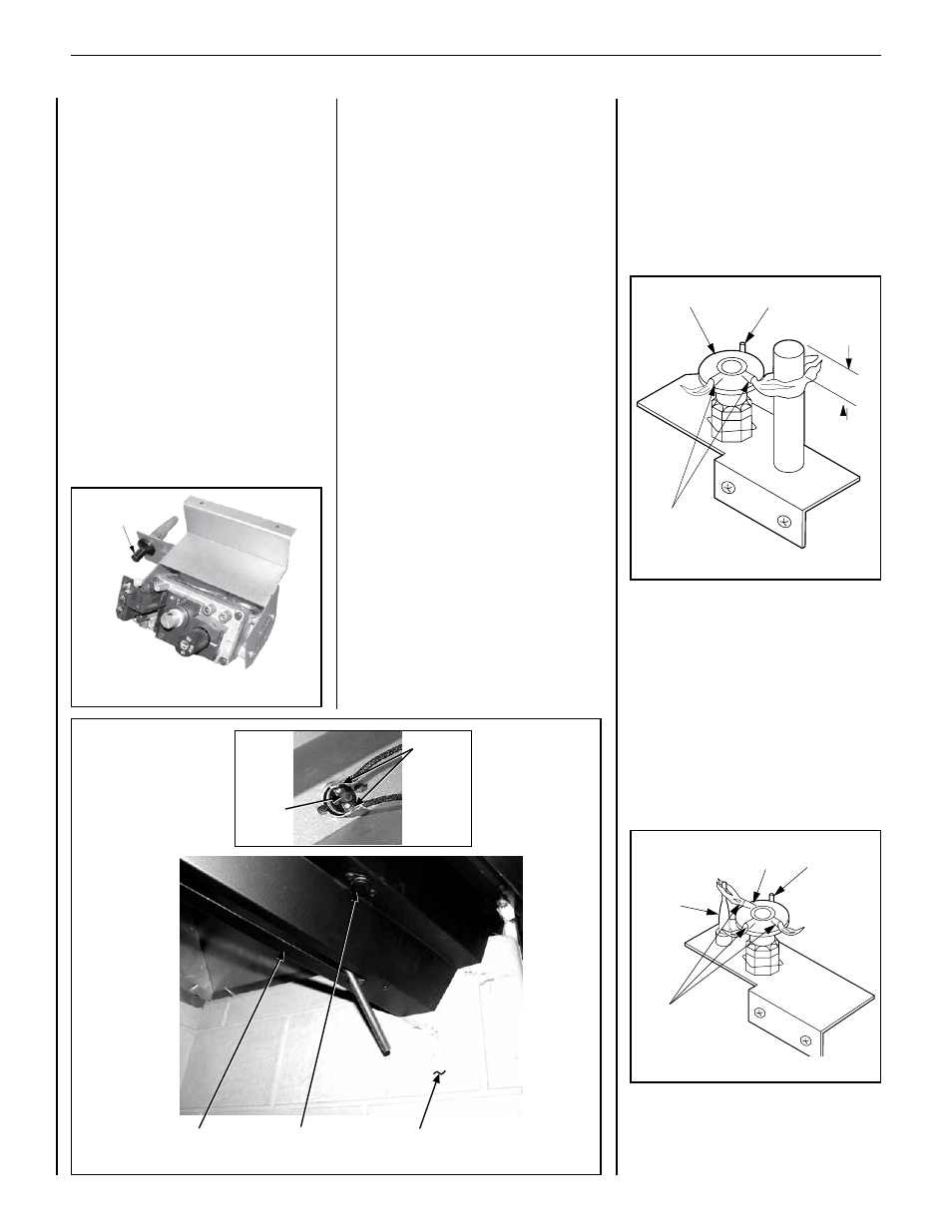
Millivolt Appliance Checkout
The pilot flame should be steady, not lifting
or floating. Flame should be blue in color with
traces of orange at the outer edge.
The top 3/8" (9 mm) at the pilot generator
(thermopile) should be engulfed in the pilot
flame. The flame should project 1" (25 mm)
beyond the hood at all three ports (Figure 27).
3/8" Min
(9 mm)
Hood
Pilot
Nozzels
Igniter Rod
Hood
Igniter Rod
Pilot
Nozzels
Flame
Sensor
Figure 25
Piezo
Igniter
SIT Valve
VERIFYING APPLIANCE OPERATION
Step 9. Checking the System – With gas line
installed run initial system checkout before
closing up the front of the unit. Follow the
pilot lighting instructions provided in the Hom-
eowner's Care and Operation Instructions. For
piezo igniter location see Figure 25 (millivolt
appliances only).
Note: Instructions are also found on the pull
out lighting instructions label attached to the
gas control valve.
When first lighting the appliance, it will take a
few minutes for the line to purge itself of air.
Once purging is complete, the pilot and burner
will light and operate as indicated in the instruc-
tion manual.
Subsequent lightings of the appliance will
not require such purging. Inspect the pilot
flame (remove logs, if necessary, handling
carefully).