PC400 Terminal Installation & User’s Guide - 23
Figure 9
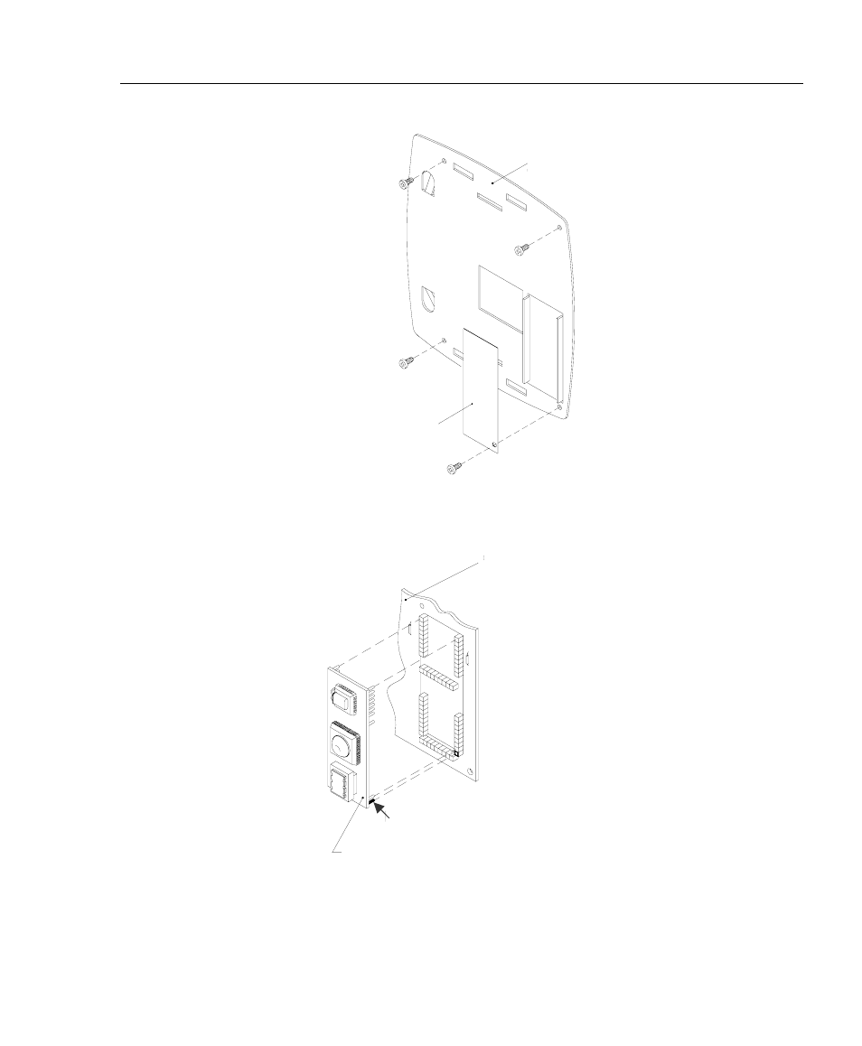
Position the modem
module so Pin-1 will be
inserted into the bottom
socket on the lower right
hand corner of the CPU
board.
PC400 Modem
Circuit Board Assembly
Pin - 1
Figure 10
Internal Cover
Plate
Cover Plate