Accessories – Lincoln Electric IDEALARC SVM136-A User Manual
Page 29
CONNECTING THE LN-8 OR LN-9 TO THE
IDEALARC CV-400
1. Set the CV-400 POWER toggle switch to the OFF (0)
position.
2. Disconnect main AC input power to the CV-400.
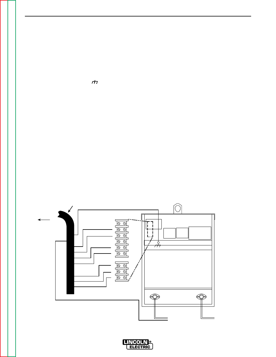
3. Connect the wire feeder control cable leads to the
CV-400 terminal strip as shown in Figure C.5.
4. Connect the wire feeder control cable ground lead
to the frame terminal marked .
5. Extend wire feeder control cable lead #21 so it can
be connected directly to the work piece.
a. Make a bolted connection using AWG #14 or
larger insulated wire. Tape the bolted connection
with insulating tape.
b. An S-16586- X remote voltage sensing work lead
is available for this purpose.
c. Keep the #21 lead electrically separate from the
work cable circuit and connection.
d. Tape the #21 lead to the work cable for ease of
use.
NOTE: Using the extended #21 lead eliminates the
need to use the LN-9's remote work lead accesso-
ry, which has a direct work lead jack.
6. Connect the LN-9 wire feeder control jumpers on
the Voltage Control board. See LN-9 operator's
manual.
NOTE: The connection diagram shown in Figure C.5
shows the electrode connected for positive polarity.
To change polarity:
a. Set the CV-400 POWER toggle switch to the OFF
(0) position.
b. Move the electrode cable to the negative (-) out-
put terminal.
c. Move the work cable to the positive (+) output
terminal.
d. Set the VOLTMETER toggle switch on power
source to negative (-).
e. Set the voltmeter toggle switch on feeder (if
equipped) to match electrode polarity.
ACCESSORIES
C-7
C-7
IDEALARC CV-400
FIGURE C.5
LN-8 OR LN-9 WIRE FEEDER CONNECTION TO THE IDEALARC CV-400
+
-
ELECTRODE
CABLE TO
AUTOMATIC
EQUIPMENT
TO
WORK
NEGATIVE
POSITIVE
TO
INPUT
CABLE
LN-8 ORLN-9
WIRE FEEDER
CONTROL CABLE
21
4
2
BLANK
31
32
75
76
77
GND
77
76
75
32
31
2
4
21
TERMINAL
STRIPS