Operation, B-4 case front controls – Lincoln Electric POWER WAVE IM713-B User Manual
Page 21
B-4
OPERATION
POWER WAVE® 655/R
B-4
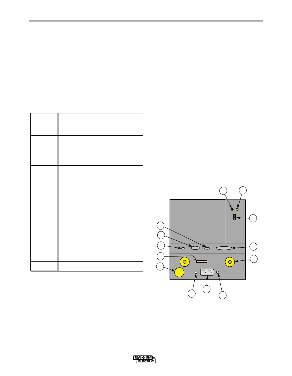
CASE FRONT CONTROLS
All operator controls and adjustments are located on
the case front of the Power Wave®. (See Figure B.1)
1. POWER SWITCH: Controls input power to the
Power Wave®.
2. STATUS LIGHT: A two color light that indicates
system errors. Normal operation is a steady green
light. Error conditions are indicated per table 4.
NOTE: The robotic Power Wave’s® status light will
flash green, and sometimes red and green, for up to
one minute when the machine is first turned on. This
is a normal situation as the machine goes through a
self test at power up.
TABLE 6
Light
Condition
Steady Green
Blinking
Green
A l t e r n a t i n g
G r e e n
a n d
Red
Steady Red
Blinking Red
Meaning
System OK. Power source communicating normal-
ly with wire feeder and its components.
Occurs during a reset, and indicates the PW-
655/R is mapping (identifying) each component
in the system. Normal for first 1-10 seconds
after power is turned on, or if the system con-
figuration is changed during operation.
Non-recoverable system fault. If the PS
Status light is flashing any combination of
red and green, errors are present in the PW-
655 /R. Read the erro r code be fore the
machine is turned off.
Error Code interpretation through the Status
light is detailed in the Service Manual.
Individual code digits are flashed in red with
a long pause between digits. If more than
one code is present, the codes will be sepa-
rated by a green light.
To clear the error, turn power source off, and
b a c k o n t o r e s e t . S e e T r o u b l e s h o o t i n g
Section.
Not applicable.
Not applicable.
3. HIGH TEMPERATURE LIGHT (thermal overload):
A yellow light that comes on when an over temper-
ature situation occurs. Output is disabled until the
machine cools down. When cool, the light goes out
and output is enabled.
4. 10 AMP WIRE FEEDER CIRCUIT BREAKER:
Protects 40 volt DC wire feeder power supply.
5. 10 AMP AUXILIARY POWER CIRCUIT BREAKER:
Protects 110 volt AC case front receptacle auxiliary
supply.
6. LEAD CONNECTOR S2 (SENSE LEAD)
7. 5-PIN ARC LINK S1
8. 5-PIN DEVICENET CONNECTOR S5
9. I / O CONNECTOR
10. NEGATIVE STUD
11. INTERFACE CONNECTOR S6
12. POSITIVE STUD
13. AUXILIARY OUTPUT
-
+
POWERWAVE
STUD
SENSE
5
LINK
5
Case Front Layout
Power Wave 655/R (Domestic/Canadian Version)
S6
1
3
2
11
12
4
13
5
9
10
8
7
6
FIGURE B.1