Warning, Operation indications, Error indications – Linear LRA User Manual
Page 23: Power-up display, Idle condition, Last gate position/condition, Pre-start delay, Reverse delay, Run timer, Entrapment
LRA Linear Residential Actuator Installation Guide
- 21 -
228158 Revision X13 2-3-2009
Operation Indications
During normal operation, the Controller’s displays will
indicate current operating conditions and status .
Power-up Display
When the Controller powers up, dashes will show on the
display for one second, then the firmware version number
will be displayed for one second .
Exiting programming restarts the Controller . The power-up
display will show upon the restart .
Idle Condition
While the Controller is idling, waiting for a command, the
display will show circulating dashes .
For DC models only - Clockwise : Batteries discharging,
Counterclockwise : Batteries charging
Last Gate Position/Condition
When the gate moves or stops, the display will show the
status for up to one minute .
Stop is displayed as
•
St
Full Close is displayed as
•
FC
Full Open is displayed as
•
FO
Entrapment is displayed as
•
En
Pre-start Delay
During the pre-start delay, the display will countdown the
number of seconds remaining before the operator starts .
Reverse Delay
If the gate travel direction is reversed from a user activation or
reversing device, and a reverse delay is set, the display will count
down the delay time in seconds before the operator restarts .
Run Timer
While the gate is opening or closing, the number of seconds
running time is displayed .
Error Indications
During abnormal operation, the Controller’s displays and
beeper will indicate the error condition that has occurred .
Entrapment
If an entrapment condition occurs detected by two repeated
open or close obstruction triggers, the Controller will lock
the operator out . The beeper will sound constantly and the
gate will not operate . To reset the Controller press the
STOP
button or press the
RESET button on the control box .
COMM LINK Connection Failure
In dual gate installations, if there is a connection failure between
the two operators, the
COMM LINK indicator will blink once a
second . During this condition the gate will not operate, except
if triggered by the
FIRE DEPT input, which functions normally .
MGT Obstacle Transmitter Trouble
If any MGT transmitters are used with the operator, their
supervision feature will alert the Controller if there is any
trouble with the transmitter . MGT transmitters send hourly
status reports and will send low battery reports when the
transmitter has a low battery . The MGT transmitters also
have a tamper detection switch that will trigger when their
case is opened .
When the Controller detects a low transmitter battery, a
tamper signal, or missing transmitter status reports, the
gate will still operate normally, but the beeper will change
as follows:
The Pre-start Alarm will beep twice as fast.
•
The Run Alarm will beep twice as fast and continue for five minutes
•
after the gate stops.
The sounder will “chirp” every five seconds when the gate is idle.
•
Correct the trouble (close case, replace battery, or replace
transmitter) to clear the obstacle transmitter trouble
indications .
Maximum Run Time Exceeded
If the Maximum Run Time is exceeded, the Controller stops
the operator the same as if a double obstacle has occurred
in an entrapment condition . The entrapment alarm sounds
constantly, and is cleared by pressing the
STOP button or the
RESET button on the cover . After the STOP or RESET button
is pressed, because the Maximum Run Time has been
exceeded, the sounder will beep twice every five seconds .
The next operation of the gate will clear the indication .
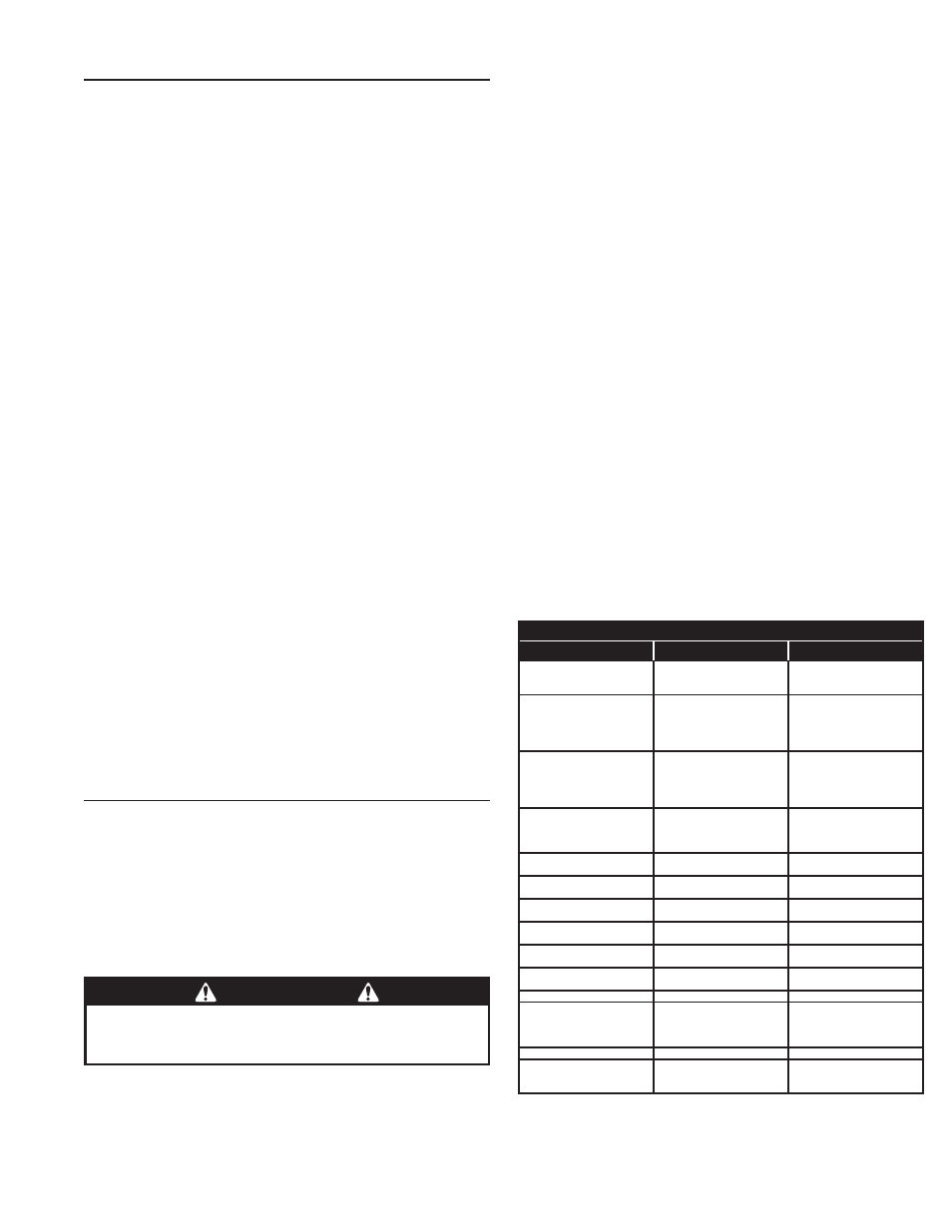
CONTROLLER ERROR CAUSES AND INDICATIONS
ERROR CAUSE
ERROR INDICATION
HOW TO CLEAR
TWO SAFETY REVERSALS (ON
SINGLE GATE OR ON EITHER
DUAL GATE)
En 00
, CONTINUOUS ALARM
BEEPER, GATE DISABLED
PRESS STOP BUTTON
MAXIMUM RUN TIMER
EXCEEDED ON OPENING
En 01
, AND
MAX RUN LED,
CONTINUOUS ALARM BEEPER,
GATE DISABLED
PRESS STOP BUTTON,
CLEARS CONTINUOUS ALARM,
THEN DOUBLE BEEP EVERY
5 SECONDS UNTIL NEXT
OPERATION
MAXIMUM RUN TIMER
EXCEEDED ON CLOSING
En 02
, AND
MAX RUN LED,
CONTINUOUS ALARM BEEPER,
GATE DISABLED
PRESS STOP BUTTON,
CLEARS CONTINUOUS ALARM,
THEN DOUBLE BEEP EVERY
5 SECONDS UNTIL NEXT
OPERATION
COMM LINK FAILURE
En 03
, AND
COMM LINK LED,
CONTINUOUS ALARM BEEPER
FOR 1 MINUTE, GATE DISABLED
(EXCEPT FOR FIRE DEPT INPUT)
PRESS STOP BUTTON, CLEARS
CONTINUOUS ALARM
GATE FULL OPEN RESULTING
FROM FIRE DEPT INPUT
En 04
, GATE DISABLED
PRESS STOP BUTTON
FAIL SAFE OR FAIL SECURE
BECAUSE OF AC POWER LOSS
En 05
, GATE DISABLED
BATTERY VOLTAGE MUST RISE
ABOVE 24 VDC
OTHER CONTROLLER IN
ENTRAPMENT (DUAL GATE)
En 06
, GATE DISABLED
CLEAR ENTRAPMENT ON OTHER
CONTROLLER (PRESS STOP)
LOW AC VOLTAGE AT
CONTROLLER
En 07
, GATE DISABLED
LOW VOLTAGE AC POWER MUST
RISE ABOVE 20 VAC
INPUT TRIGGERED DURING
ENTRAPMENT LOCKOUT
En 08
, GATE DISABLED
PRESS STOP BUTTON
COMPATIBILITY PROBLEM
En 09
, GATE DISABLED
UPDATE FIRMWARE AND RESET
BOTH PAIRED CONTROLLERS
EEPROM PROBLEM
En 10
, GATE DISABLED
TRY RESET, CALL TECH. SUPPORT
DC MOTOR MISMATCH
En 11
, GATE DISABLED
REPROGRAM MOTOR TYPE OR
CHANGE DC MOTOR BOARD,
NEXT GATE MOVEMENT WILL
RETRY DC MOTOR CHECK
MOTOR FAILURE
En 12
, GATE DISABLED
REPLACE MOTOR
MGT SUPERVISORY CONDITION
(TAMPER, LOW BATTERY,
MISSING HOURLY STATUS)
FAST BEEPS DURING PRESTART,
FAST BEEP RUN ALARM, CHIRP
EVERY 5 SECONDS AT IDLE
CLEARS WHEN MGT CONDITION
CLEARS
WARNING
The Stop and/or Reset button must be located in the line-of-
sight of the gate. Activation of the reset control shall not
cause the operator to start.