Warning, Safety edge layout illustration – Linear LRA User Manual
Page 20
LRA Linear Residential Actuator Installation Guide
- 18 -
228158 Revision X13 2-3-2009
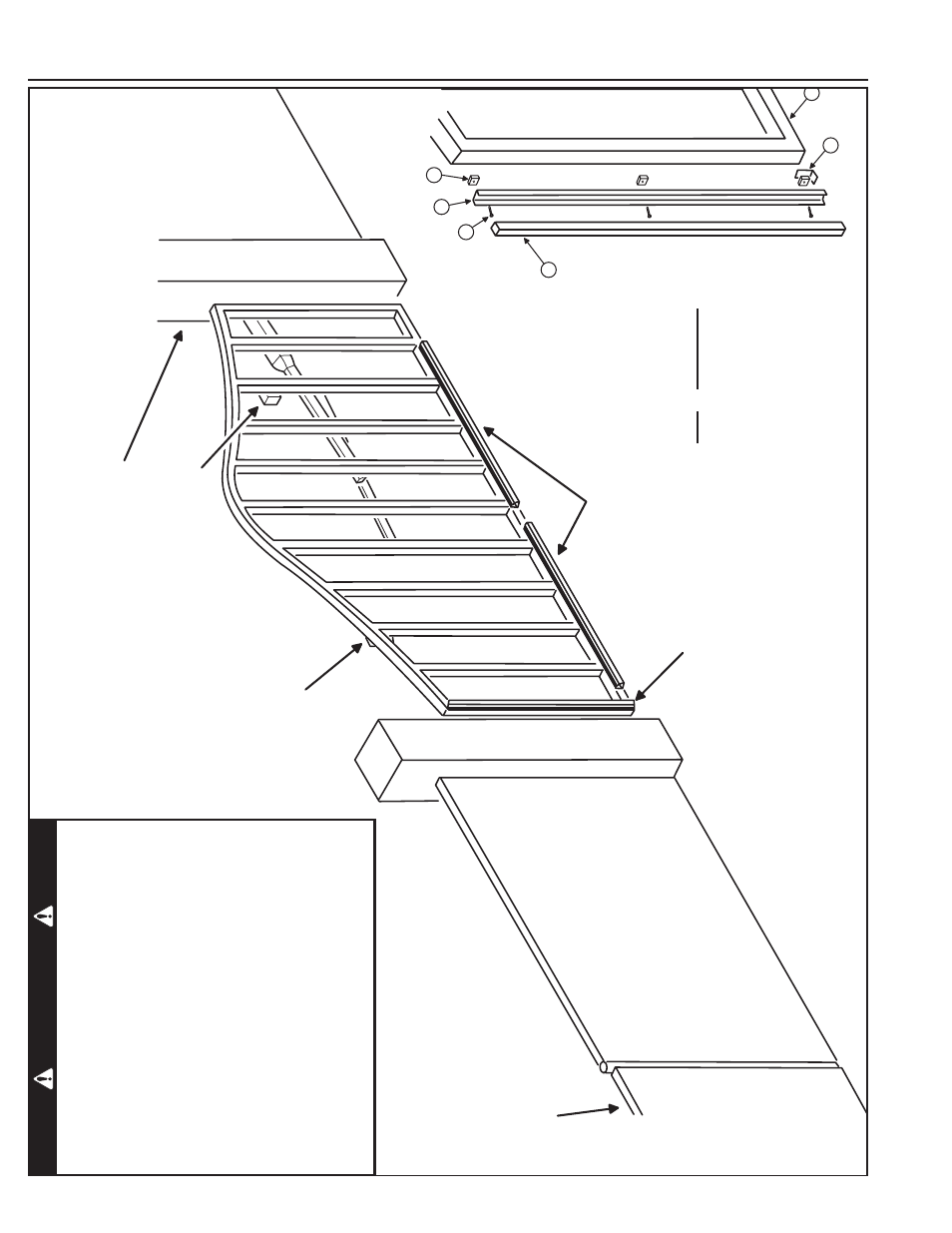
Safety Edge Layout Illustration
RE
CE
IV
ER
F
O
R
G
AT
E
ED
G
E
TR
AN
SM
IT
TE
R
BU
IL
T
IN
TO
C
O
NT
RO
LL
ER
G
AT
E
ED
G
E
TR
AN
SM
IT
TE
R
#1
SE
PA
RA
TE
P
ED
ES
TR
IA
N
GATE REQUIRED
7F
T.
M
IN
IM
UM
D
IS
TA
NC
E
AW
AY
F
RO
M
G
AT
E
ED
G
E
M
O
UN
TE
D
O
N
LE
AD
IN
G
O
UT
SI
DE
E
DG
E
OF GATE
ED
G
ES
M
O
UN
TE
D
AC
RO
SS
BO
TT
O
M
O
F
G
AT
E
W
IR
E
ED
G
ES
S
HO
W
N
TO
T
HE
C
LO
SE
O
BS
TR
UC
TI
O
N
IN
PU
T
O
NL
Y
O
R
TO
W
IR
EL
ES
S
G
AT
E
ED
G
E
TR
AN
SM
IT
TE
RS
IT
EM
D
ES
CR
IP
TI
O
N
1
G
AT
E
(R
EF
ER
EN
CE
O
NL
Y)
2 EDGE
3
E
DG
E
EX
TR
US
IO
N
4 SPACERS (3
)
5
8
-3
2
X
1"
S
CR
EW
S
(3
)
6 RETAINING BRACKET
RE
VE
RS
IN
G
E
DG
E
AS
SE
M
BL
Y
CL
O
SE
-U
P
5
1
2
3
4
6
G
AT
E
ED
G
E
TR
AN
SM
IT
TE
R
#2
W
ARNING
One
or
more
contact
sensors
shall
be
located
on
the
inside
and
outside
leading
edge
of
a
swing
gate.
Additionally
,
if
the
bottom
edge
of
a
swing
gate
is
greater
than
six
inches
(152
mm)
above
the
ground
at
any
point
in
its
arc
of
travel,
one
or
more
contact
sensors shall be located on the bottom edge. A
hardwired
contact
sensor
shall
be
located
and
its
wiring
arranged
so
that
the
communication
between
the
sensor
and
the
gate
operator
is
not
subjected
to
mechanical damage. A
wireless
contact
sensor
such
as
one
that
transmits
radio
frequency
(RF)
signals
to
the
gate
operator
for
entrapment
protection
functions
shall
be
located
where
the
transmission
of
the
signals
are
not
obstructed
or
impeded
by
building
structures,
natural
landscaping
or
similar
obstruction.
A
wireless
contact
sensor
shall
function under the intended end-use conditions.