See figure f.22, Troubleshooting & repair – Lincoln Electric VANTAGE 400 User Manual
Page 147
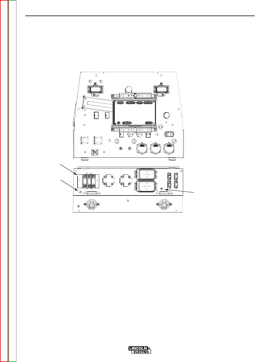
50 Amp
Circuit
Breaker
Ground
Screw
Aux. Power Stud
(Panel Left Side)
FIGURE F.22 – CONTROL & OUTPUT PANELS - REAR VIEW
STATOR/ROTOR REMOVAL AND REPLACEMENT PROCEDURE
(CONTINUED)
1. Using a 7/16” wrench, disconnect stator lead #6
from the auxiliary power stud on the left side of
the control box. See Figure F.22.
17. With a 3/8” wrench, disconnect lead #5 from
the center ground stud (nearest the control
transformer). See Figure F.22.
18. Using a phillips screw driver, remove lead #3
from the top 50A circuit breaker for the
120/240V receptacle. See Figure F.22.
NOTE: This lead must be wound two turns clock-
wise through the toroid (opposite in direction from
leads #6A).
19. Disconnect lead #5A from the auxiliary power
ground stud (left side of the control box, next
to the 120V circuit breaker). See Figure F.22.
20. Using a 3/8” wrench, remove the two screws
holding the control box to the top of the fan
baffle.
TROUBLESHOOTING & REPAIR
F-99
F-99
VANTAGE® 400