3 connectors on back of unit, Figure 2 rear view, Table 1 description of indicators and connectors – Liebert EM User Manual
Page 9: Connectors on back of unit, Figure 2, Rear view, Description of indicators and connectors
Introduction
3
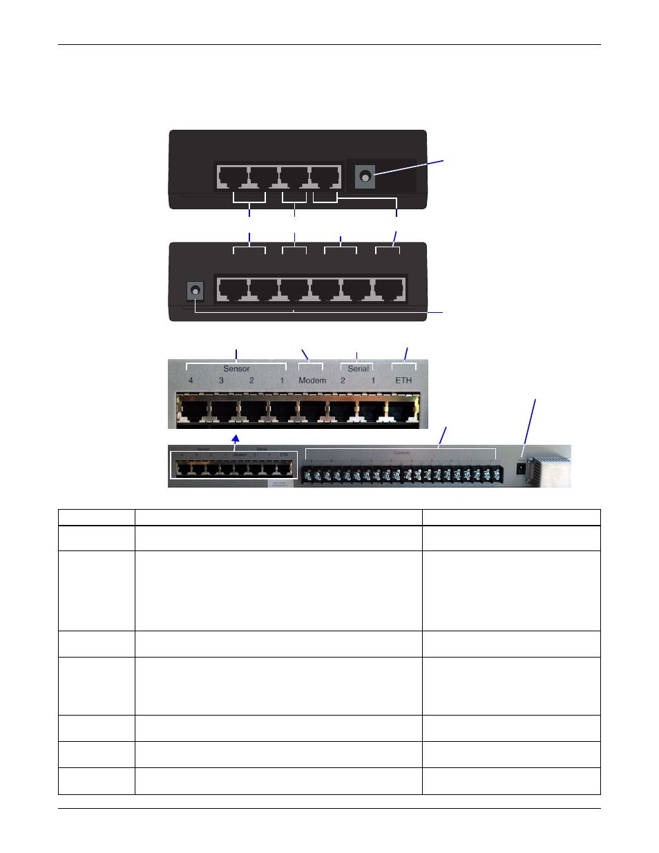
1.1.3 Connectors on Back of Unit
The back of the OpenComms EM, shown in Figure 2, has an input power source, sensor ports, a
modem port and an Ethernet port. The EM PDU and vEM-14 controllers have serial ports, and
vEM-14 controllers also have 10 dry contact inputs.
Figure 2
Rear view
Table 1
Description of indicators and connectors
Item
Description
For more information, see:
A - Power and
port indicators
Indicators on the front of the unit show the status of input power
and other connections (see Figure 1).
Sensor ports to connect compatible sensors:
• Temperature sensor
(provided with TMNET & TMPDUNET kits)
• Temperature & humidity combination sensor
(provided with THCMNET & THCMPDUNET kits)
• Humidity, water detection or dry-contact sensor
(available separately)
Port for connection to a modem.
• Requires RJ45 cable (customer-supplied)
Serial 1 and Serial 2 ports to connect serial devices
(EM PDU and vEM-14 controllers).
• Requires serial cable (one provided)
Port for connection to an Ethernet network.
• Requires RJ45 cable (customer-supplied)
2.3.2: Connect to an Ethernet Network
5.7.1: Network Connectivity
Power connection for the OpenComms EM.
• Requires 9VDC
2.3.1: Connect Power to the Unit
10 dry contact inputs for auxiliary devices (vEM-14 controller).
• Requires Form C dry contacts
—
Sensor
2
Sensor
1
Modem DCN
Ethernet
EM
CONTROLLER
F - Power
B - Sensors
C - Modem
EM PDU
CONTROLLER
Sensor
2
Sensor
1
Serial
2
Serial
1
Modem
DCN Ethernet
D - Serial
devices
E - Ethernet
vEM-14
CONTROLLER
G - Dry
contact
inputs