2 indicators, Figure 3 indicators on front of unit, Table 2 indicators summary – Liebert EM User Manual
Page 10: Indicators, Figure 3, Indicators on front of unit, Table 2, Indicators summary
Introduction
4
1.2
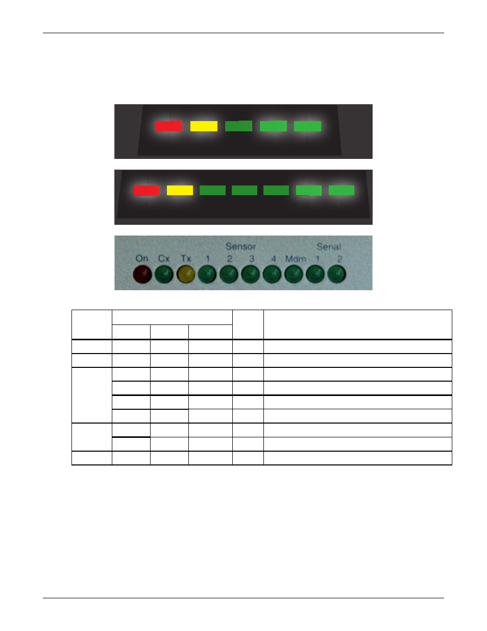
Indicators
The front of the OpenComms EM has indicators that show input power to the unit and the status of
various connections, as shown in Figure 3 and described in Table 2.
Figure 3
Indicators on front of unit
EM CONTROLLER
EM PDU CONTROLLER
vEM-14 CONTROLLER
Table 2
Indicators summary
Indicator
Type
Indicator Label on Model:
Color
Description
EM
EM PDU
vEM-14
Power
Power
Power
On
Red
Power is connected and powering the OpenComms EM.
Ethernet
Link
Link
Cx/Tx
Yellow
The OpenComms EM is connected to an active network.
Sensor
port
Sensor 1
Sensor 1
Sensor 1
Green
A sensor is connected to the Sensor 1 port.
Sensor 2
Sensor 2
Sensor 2
Green
A sensor is connected to the Sensor 2 port.
—
—
Sensor 3**
Green
A sensor is connected to the Sensor 3 port.
—
—
Sensor 4**
Green
A sensor is connected to the Sensor 4 port.
Serial
port*
—
Serial 1
Serial 1
Green
A device is connected to the Serial 1 port.
—
Serial 2
Serial 2
Green
A device is connected to the Serial 2 port.
Modem
Activity
Modem
Mdm
Green
A modem is connected.
* EM PDU and vEM-14 controllers
** vEM-14 controllers
Power Link Activity Sensor
1
Sensor
2
Power Link Serial
1
Modem
Serial
2
Sensor
1
Sensor
2