4 thresholds in the web interface, 1 temperature/humidity sensor thresholds, 2 dry-contact sensor thresholds – Liebert EM User Manual
Page 19: Thresholds in the web interface, Temperature/humidity sensor thresholds, Dry-contact sensor thresholds, Table 7, Table 8
Web Interface Overview
13
4.4
Thresholds in the Web Interface
The OpenComms EM collects data from connected sensors at regular intervals. When a reading
crosses a user-defined threshold:
• The sensor’s status changes.
• Alerts are sent—if the unit is configured for e-mail, pager or SNMP trap alerts.
4.4.1 Temperature/Humidity Sensor Thresholds
Temperature and humidity sensors have four thresholds: High Critical, High Warning, Low Warning
and Low Critical. The Normal range is determined by these limits. Table 7 shows examples of limits
for these types of sensors. Each level is color-coded in the Web interface for easy identification.
Using the examples of temperature sensor limits in Table 7, the following is a typical scenario:
• The temperature of a monitored area rises to 90°F. The status changes at two points:
• The status changes to High Warning when the temperature reaches 75°F. The name of the
sensor, the current reading and the status are displayed in yellow text in the Web interface.
• As the temperature continues to rise, the status changes to High Critical at 85°F (displayed
in red text).
• At each change in status, the unit sends alerts if it is configured to do so.
• When the temperature falls to 74°F, the status changes to Normal (displayed in green text) and a
return-to-normal alert is sent if the unit is configured to send alerts.
• When a sensor is disconnected from the unit, its status changes to Not Present (black text) and
the sensor’s name appears in gray text.
4.4.2 Dry-Contact Sensor Thresholds
A dry-contact sensor has only two states: Normal and Critical, as shown in Table 8. The user
defines Normal as either Normally Open or Normally Closed and the OpenComms EM designates the
opposite state as Critical.
Using the examples for a dry-contact sensor in Table 8, the following is a typical scenario:
• The sensor’s normal state is defined as Normally Open.
• When the contact closes, the sensor’s status changes to Critical (displayed in red text). The unit
sends alerts, if it is configured to do so.
• When the state changes again (the contact opens), the sensor’s status changes to Normal (dis-
played in green text) and a return-to-normal alert is sent if the unit is configured to send alerts.
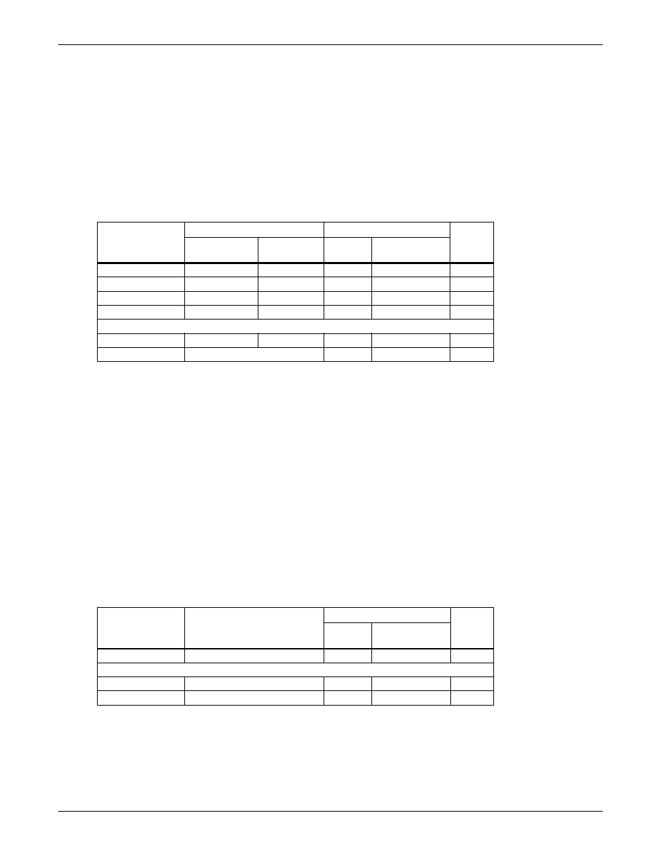
Table 7
Examples of sensor limits - temperature and humidity sensors
Limit
Examples of Limits
Text Display Color
Graph
Line
Color
Temperature
(°F)
Humidity
(% RH)
Sensor
Name
Status &
Current Value
High Critical
85
55
Red
Red
Red
High Warning
75
50
Yellow
Yellow
Yellow
Low Warning
65
30
Yellow
Yellow
Yellow
Low Critical
60
25
Red
Red
Red
Other conditions
Normal
66°F to 74°F
31% to 49%
Green
Green
—
Not Present
(sensor is not connected)
Gray
Black
—
Table 8
Examples of sensor limits - temperature and humidity sensors
Limit
Example of
User-Defined State
Text Display Color
Graph
Line
Color
Sensor
Name
Status &
Current Value
Critical
Closed
Red
Red
Red
Other conditions
Normal
Normally Open
Green
Green
—
Not Present
(sensor is not connected)
Gray
Black
—