Locke MP-3132 User Manual
Page 9
1-1 INTRODUCTION
We are pleased to have you as a Locke Turf
customer. Your MP-3132 or FP-3132 has been
carefully designed to give maximum service with
minimum down time. This manual is provided to give
you the necessary operating and maintenance
instructions for keeping your mower in top operating
condition. Please read this manual thoroughly.
Understand what each control is for and how to use it.
Observe all safety precautions decaled on the
machine and noted throughout the manual for safe
operation of the implement. If any assistance or
additional information is needed, contact your
authorized Locke Turf distributor.
NOTE
All references made to right, left, front, rear, top or
bottom is as viewed facing the direction of travel with
implement properly attached to tractor.
Technical Specifications
Specification
MP and FP
Cutting Width
11’
Transport Width
78”
Cutting Height
1/2" to 4”
Blade Tip Speed (FPM) 15,000 FPM
Required Tractor PTO HP
45HP min.
Wing Flex
30° up, 10° down
Belts
Cat. IV 80° CV (main)
Driveline Size
Cat. III (wing)
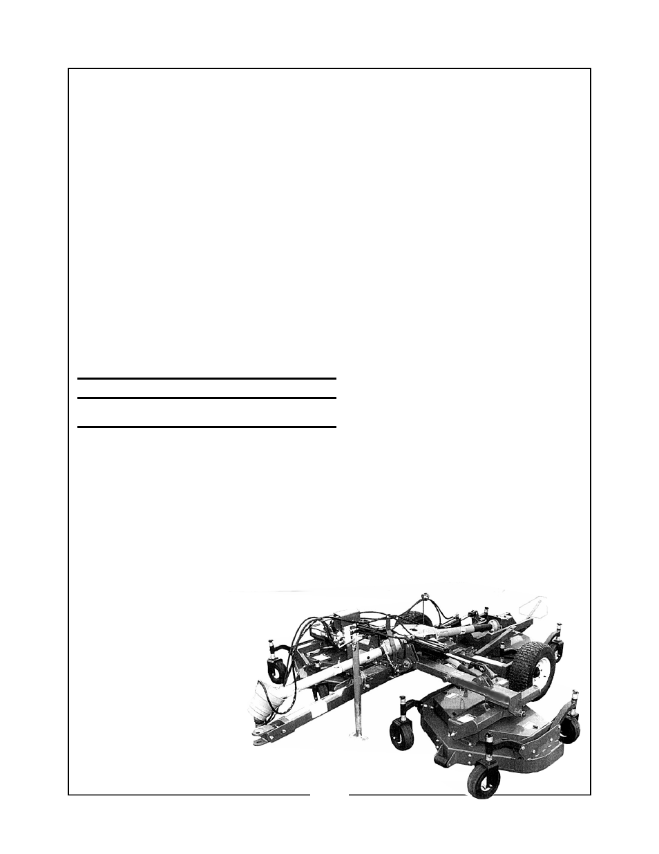
1-2 DESCRIPTION
The MP-3132, (figure 1-1), is designed for turf
maintenance applications where a high quality
of cut on turf grasses is required.
Three sets of counter- rotating blades (per
deck) continue to cut the grass clippings sev-
eral times before allowing the tiny pieces to
fall to the ground. This eliminates a build up
of grass residue on top of the turf. (the FP-
3132 is exactly like the MP-3132 minus the
mulching blades) The caster wheel arrange-
ment along with the flexible, floating deck at-
tachment, the standard front mounted rollers
and the under deck roller all work together to
give an even cut and minimize scalping.
NOTE: The inside rear wheel on the wing
mower decks and both the front wheels on the
rear mower deck are rigidly mounted and are
not designed to caste.
Power from the tractor is transmitted through
a telescoping driveline to a gearbox arrange-
ment, which allows either wing unit to be
folded up to 30° while still operating. Power is
passed to the spindle housings by a B-
section, Kevlar reinforced belt. Drive train
protection is provided by belt slippage.
SECTION I
INTRODUCTION AND DESCRIPTION
7