Locke MP-3132 User Manual
Page 24
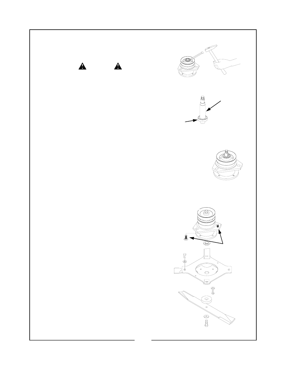
9. Remove the blade carrier wrench and restake the
blade carrier into the notch of the outer shaft.
(Figure 13)
USE SAFETY EYE PROTECTION
WHEN USING HAMMER AND PUNCH
TO PREVENT FLYING PARTICLES
FROM INJURING EYES.
10. Restake the drive sheave into the notch of the outer
shaft. (Figure 13)
11. Press the bottom inner bearing on the lower
end of the inner shaft. (Figure 14)
12. Place the inner shaft and lower bearing
through the outer shaft and top inner bearing.
Press together until the top bearing has bot-
tomed out on the shaft and the bottom bearing
has bottomed out in the outer shaft. The top
and bottom bearings will be recessed in the
outer shaft. (Figure 15)
13. Install the Woodruff key, sheave, flatwasher
and nut onto the inner shaft. TORQUE NUT
TO 76 FT.LBS.
NOTE
Before installing upper blade assembly, install the
three 1/2" x 1-1/2” carriage bolts into the spin-
dle housing. (Figure 16)
14. Place the shaft bushing on the spindle shaft.
Using the (4) 3/8” x ¾” capscrews and Belle-
ville washer, bolt the blade assembly to the
blade carriers. TORQUE TO 32 FT.LBS.
15 Using safety gloves, install the shaft washer,
lower blade, Belleville washer and blade bolt
onto the inner shaft. TORQUE TO 76 FT.LBS.
CAUTION
Figure 13
Figure 14
Figure 15
Figure 16
Inner Shaft
Bottom Inner
Bearing
1/2” x 1-1/2”
Carriage Bolts
22