Caution – Locke MP-3132 User Manual
Page 16
Driving Sheave
At Gearbox
Lower Adjustment
Rod & Spring
2-7/8"
4-5 BLADE REPLACEMENT
WEAR HEAVY WORK GLOVES TO PROTECT
HANDS FROM SHARP EDGES. WHEN TURNING
BLADES, BE AWARE OF OPPOSITE BLADE AP-
PROACHING.
A complete spare set of blades comes with the cutter.
The lower blades are pinned on the frame and the up-
per blades are stored in the tool box. (Figure 4-4)
Always replace all (4) blades on an assembly to retain
balance. In addition to replacing blades when they
become worn and dull, they should also be replaced if
the uplift angle on the trailing side of the blade be-
comes worn off. As the angle wears down, the mulch-
ing action deteriorates.
A.
Raise the cutter using the tractor hydraulic
system and use transport locks before changing
blades.
B. Turn off tractor, set parking brake and remove
key.
C. Remove bolt and Belleville washer securing
bottom blade to spindle. Remove blade. Shaft
washer will come off with the blade. (Figure 4-5)
CAUTION
D.
Remove the four 3/8” x 1” capscrews and
Belleville washers from the upper mulching assembly.
Remove mulching assembly. The blade bushing will
come off with the mulching assembly.
E.
Remove the 3/8” –24 UNF x 7/8” Gr. 8 blade
bolt and nut for each blade. Inspect the blade nut
shoulder and the blade bolts for wear. Replace if nec-
essary.
F.
When installing new blades on the mulching
assembly, make sure that two blades are installed on
the top side of the assembly 180° from each other and
two on the bottom side of the assembly. The blades
must mount on the rotation “pads” for proper operation.
Assemble the (4) new blades to the blade holder using
the blade nuts, bolts and flatwashers. Tighten the
bolts to 45 ft./lbs.
G.
Insert the blade bushing in the center of the
mulching assembly so that the bushing flange is on the
top side of the assembly. Slide the mulching assembly
and flanged bushing over the spindle shaft and secure
mulching assembly to the upper blade carrier using the
(4) 3/8” – 16 UNC x 3/4" Gr. 5 bolts and Belleville
washers. Torque all (4) mulching assembly attach-
ing bolts to 31 ft./lbs
H.
Install the blade washer over the spindle
shaft. Install the bottom blade and torque the 1/2" –
20 UNF Gr. 8 bolt to 76 ft./lbs. Note: The concave
side of the Belleville washer must be toward the
blades. Do not substitute with a flatwasher.
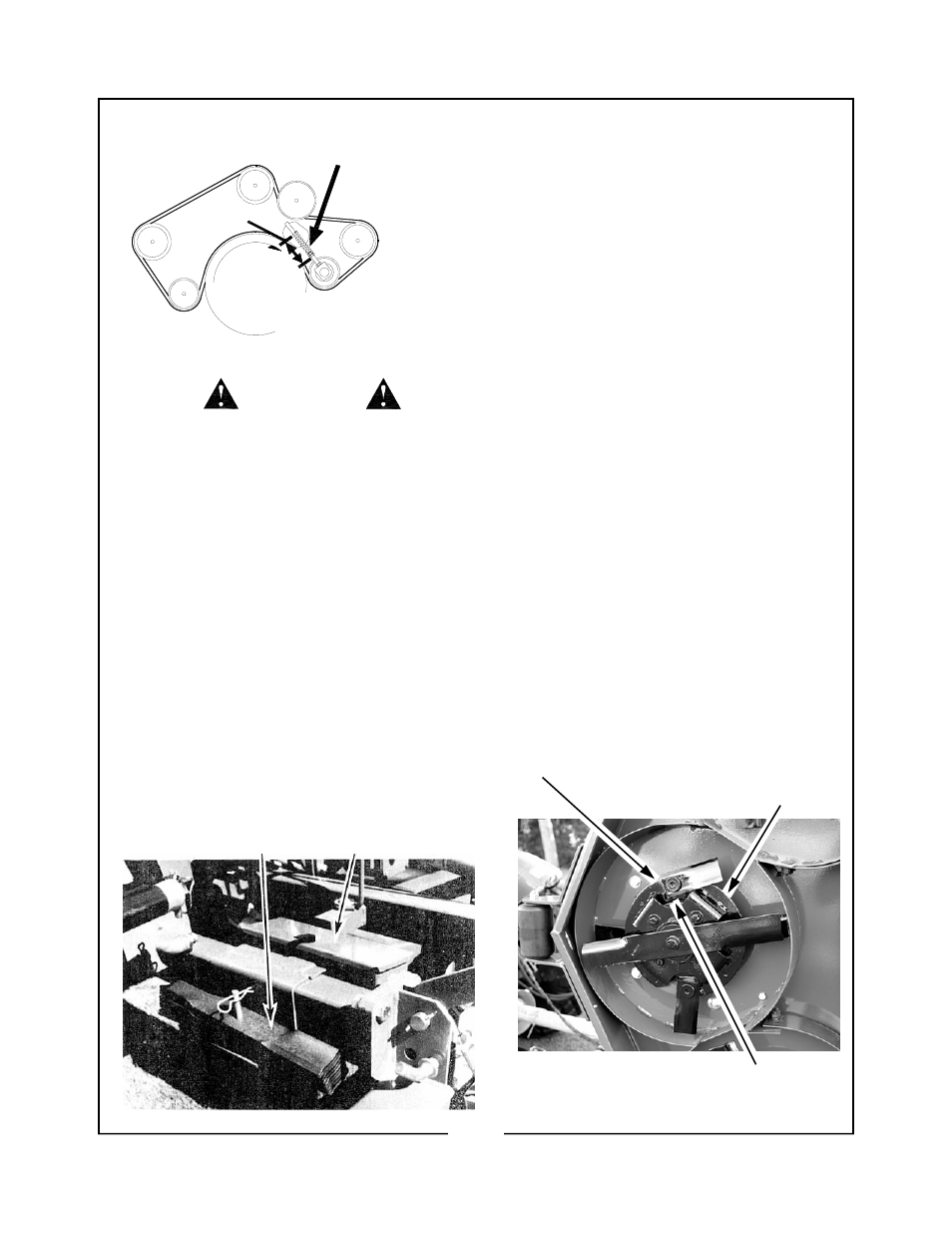
Figure 4-5 Blade Arrangement
3/8” - 24 UNF x 7/8” Gr. 8 Blade Bolt & Blade Nut
Upper
Blade
Assembly
Rotation Pad
14
Figure 4-4 Spare Blades and Tool Box