Accessories – Lincoln Electric MAXSA IM10024 User Manual
Page 24
C-2
ACCESSORIES
C-2
SUBMERGED ARC CONTACT
ASSEMBLIES
K231-[X/XX] CONTACT NOZZLE
The K231- [x/xx] is used for submerged arc weld-
ing with currents generally under 600 amps.
Higher currents can be used but result in some-
what faster tip wear. The outer flux cone deposits
flux around the arc for full coverage with mini-
mum flux consumption.
Contact tips for the electrode diameter specified
on the order are shipped with each nozzle. A dif-
ferent contact tip is required for each electrode
diameter used.
Installation
- Nozzles ordered for 3/32” (2.4 mm)
electrode include a liner and a contact tip
adapter. Screw the adapter into the end of the
nozzle and the contact tip into the adapter.
Insert the outgoing wire guide from the wire feed
head into the top of the K231 and install the
assembly in position on the bottom of the wire
feed head. Lock it in position using the two
clamps provided with the head.
Connect one end of the rubber flux hose to the
tube at the bottom of the flux hopper. Fit the
short copper tube in the other end of the rubber
hose then insert the copper tube into the hole in
the flux cone body. See Figure C.1
CAUTION
- Pushing the copper tube too far into
the flux cone body will cause a short
between the cone and nozzle if the
cone touches the work.
Connect the lug on the electrode cables from the
power source to the tab on the contact nozzle
and tighten the bolt and nut. See Figure C.1.
Operation
- DO NOT completely straighten the
electrode. A slight curvature is required in the
electrode to insure good electrical contact inside
the contact tip.
Maintenance
- Replace the contact tip when it
no longer provides accurate wire location or good
electrical contact. Rusty and dirty wire or exces-
sively high currents increase tip wear. Always
keep replacement tips in stock.
To replace the contact tip, first loosen the retain-
ing wing nut and remove the flux cone body.
Then unscrew the tip and replace it.
A special socket head screw holds the nozzle
body to the insulator. If the nozzle body becomes
loose, remove the nozzle from the head, tighten
the screw and reassemble nozzle.
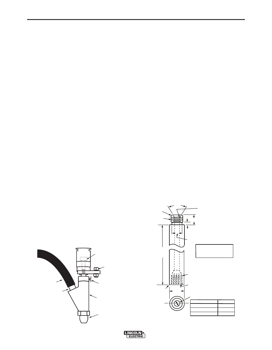
Extensions
- The K231 nozzle can be extended
if necessary. Order part number S12003 for a 5”
(127mm) extension or make any length per draw-
ing in Figure C.2.
MAXsa™ 22 & 29 WIRE DRIVES
1/2”
1/8”
1/2”
60°
+
_ 2°
9/16-18
Class 2 Fit
1/32”x45°
Chamfer
As
Req’d
Break
Corner
3/4”
33/64”Drill 11/16” deep
9/16-18 Tap 9/16” deep
Class 2 Fit
1/32”x45°
Chamfer
“A” Dia. (See Table)
Remove Sharp
Corner
Wire Size
“A” Dim.
5/64-3/32(2.0-2.4mm) 1/8 (3.2mm)
1.8-5/32 (3.2-4.0mm) 3/16 (4.8mm)
3/16 -7/32(4.8-5.6mm) 1/4 (6.4mm)
Material - Hard Drawn
Copper or Heat Treatable
Copper Alloy
FIGURE C.2 - EXTENSION
FIGURE C.1 - K231
Weld Cable
Connection
Flux
Hose
Copper
Tube
Wing
Screw
Flux Cone
Body
Flux Cone
Socket Head
Screw