Troubleshooting and repair – Lincoln Electric INVERTEC SVM199-A User Manual
Page 54
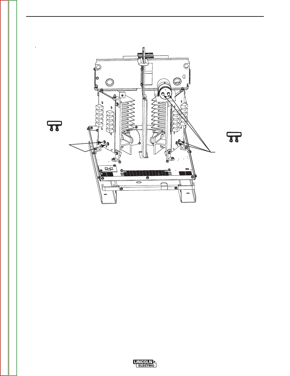
CAPACITOR
TERMINALS
RESISTOR
CAPACITOR
TERMINALS
RESISTOR
CAPACITOR
TERMINALS
RESISTOR
CAPACITOR
TERMINALS
RESISTOR
FIGURE F.1 – CAPACITOR TERMINAL LOCATION
INPUT FILTER CAPACITOR DISCHARGE PROCEDURE (continued)
PROCEDURE
1. Remove input power to the INVERTEC® V450-
PRO.
2. Using the 3/8” nut driver, remove the left and
right case sides.
3. Be careful not to make contact with the capaci-
tor terminals that are located in the bottom cen-
ter of the left and right side switch boards. See
Figure F.1.
4. Carefully check for a DC voltage at the capaci-
tor terminals on both boards. Note the polarity
is marked on the PC board and also lead #19 is
positive.
5. If any voltage is present, proceed to Step #6. If
no voltage is present, the capacitors are dis-
charged.
NOTE: Normally the capacitors discharge in about
two minutes after input power is removed.
6. Using the high wattage resistor (25-1000 ohms
@ 25 watts (minimum), electrically insulated
gloves and pliers, connect the resistor across
the two capacitor terminals. Hold the resistor in
place for 10 seconds. DO NOT TOUCH THE
CAPACITOR TERMI-NALS WITH YOUR BARE
HANDS. NEVER USE A SOLID CONDUCTOR
W/LESS THAN 25 OHM RESISTANCE FOR
THIS PROCEDURE.
7. Repeat procedure for the other capacitor.
8. Recheck the voltage across the capacitor termi-
nals. The voltage should be zero. If any volt-
age remains, repeat the discharge procedure.
TROUBLESHOOTING AND REPAIR
F-14
F-14
INVERTEC® V450-PRO