Installation, Connections of wire feeders to v450-pro – Lincoln Electric INVERTEC SVM199-A User Manual
Page 14
INSTALLATION
A-6
A-6
INVERTEC® V450-PRO
CONNECTIONS OF WIRE FEEDERS TO V450-PRO
LF-72, 74 Connection Instructions
• Turn the Invertec® power switch "off".
• Connect the K1797-[ ] control cable from the LF-72, 74
to the 14-pin MS-style connector.
• Connect the electrode cable to the output terminal of the
polarity required by electrode. Connect the work lead to
the other terminal.
• If a remote control such as K857 is to be used with the
LF-72, 74 the remote can be connected directly to the 6-
pin MS-style connector on the front of the Invertec® or
use a K864 adapter to connect the LF-72, 74 and the
remote to the 14-pin MS-style connector.
LN-10, DH-10 Connection Instructions
• Turn the Invertec® power switch "off"
• Connect the K1505 control cable from the LN-10 to the
14-pin MS-style connector.
• Connect the electrode cable to the output terminal of
polarity required by the electrode. Connect the work lead
to the other terminal.
• Set the meter polarity switch on the front of the Invertec®
to coincide with wire feeder polarity used.
• See the LN-10 manual for details on accessing Control
DIP Switch. Dip Switches for the V350 and the same set-
tings may be used for the V450.
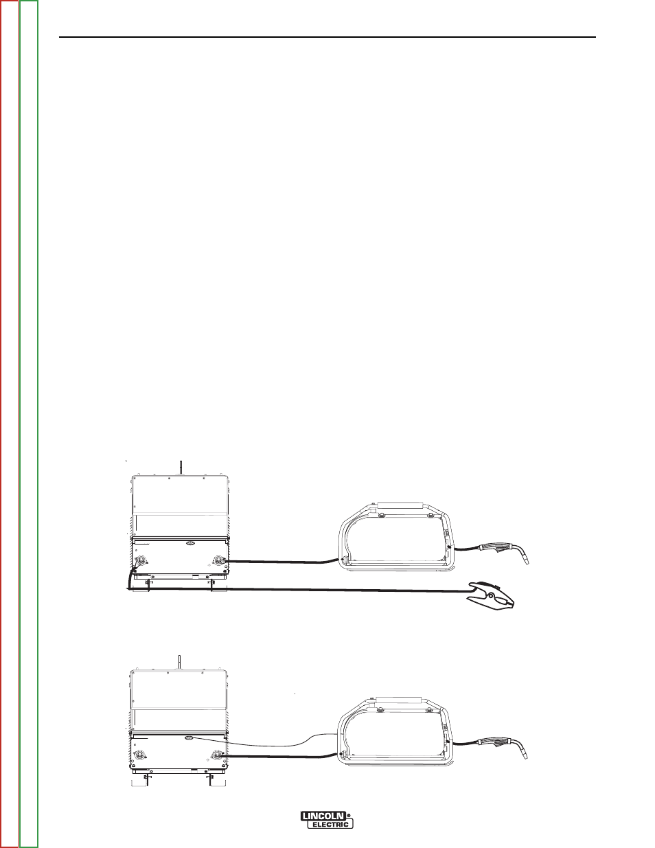
LN-15 Connection Instructions
(See Figure A.4)
• Turn the Invertec® power switch "off".
• Connect the electrode cable to the output terminal of polar-
ity required by electrode. (See Figures below)
• Set the meter polarity switch on the front of the Invertec®
to coincide with wire feeder polarity used.
LN-25 Connection Instructions
• Turn the Invertec® power switch "off".
• Connect the electrode cable to the output terminal of polar-
ity required by electrode. Connect the work lead to the
other terminal.
• LN-25 with Remote Control 6-Pin (K444-1) and 14-pin
(K444-2) remotes can be connected directly to the 6-pin &
14-pin MS-style connectors. The 42 Volt Remote Voltage
and Output Control (K624-1) Kit can be connected to the
V450’s 14-pin MS-style connector using Remote Control
Cable assembly K627- [ ]. LN-25s with a K431-1 remote kit
can be connected to the V450’s 14-pin MS-style connector
using a K432 cable and K876 adapter. (See connection
diagram S19899). Or the K432 cable could be modified
with a K867 Universal Adapter Plug (See connection dia-
gram S19405) to connect it to the V450’s 14-pin MS-style
connector.
14-PIN
STUD
WORK CLAMP
ELECTRODE CABLE
V450-PRO
ACROSS THE ARC MODEL
CONROL CABLE MODEL
OUTPUT TERMINALS
ALWAYS HOT.
POWER SOURCE CONTACTOR
SWITCH MUST BE IN THE
“ON” POSITION OR USE A
K848 JUMPER PLUG KIT.
MAGNUM GUN
AND CABLE
ASSEMBLY
LN-15
SEMIAUTOMATIC
WIRE FEEDER
K1870-1
14-PIN
STUD
ELECTRODE CABLE
V450-PRO
K1819-10
CONTROL CABLE
MAGNUM GUN
AND CABLE
ASSEMBLY
LN-15
SEMIAUTOMATIC
WIRE FEEDER
K1871-1 MODEL
14-PIN
STUD
WORK CLAMP
ELECTRODE CABLE
V450-PRO
ACROSS THE ARC MODEL
CONROL CABLE MODEL
OUTPUT TERMINALS
ALWAYS HOT.
POWER SOURCE CONTACTOR
SWITCH MUST BE IN THE
“ON” POSITION OR USE A
K848 JUMPER PLUG KIT.
MAGNUM GUN
AND CABLE
ASSEMBLY
LN-15
SEMIAUTOMATIC
WIRE FEEDER
K1870-1
14-PIN
STUD
ELECTRODE CABLE
V450-PRO
K1819-10
CONTROL CABLE
MAGNUM GUN
AND CABLE
ASSEMBLY
LN-15
SEMIAUTOMATIC
WIRE FEEDER
K1871-1 MODEL
FIGURE A.4