The machine schematic, Electrical diagrams, Control panel – Lincoln Electric INVERTEC SVM199-A User Manual
Page 129: Control board, Case front detail, Invertec® v450-pro
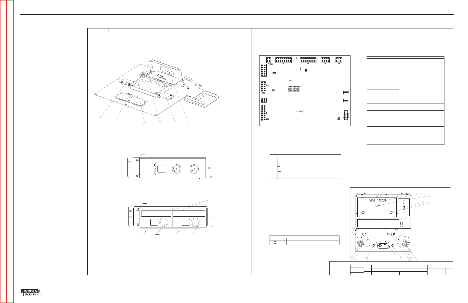
ELECTRICAL DIAGRAMS
G-5
INVERTEC® V450-PRO
SCHEMATIC - COMPLETE MACHINE - (G4875 SHEET 3)
G4875
INVERTEC V450-PRO
MACHINE SCHEMATIC
NONE
G4421
DO NOT SCALE THIS DRAWING
EQUIPMENT TYPE:
SUBJECT:
SCALE:
UF
CRM36847
3
PAGE ___ OF ___
3
ENGINEERING CONTROLLED
MANUFACTURER:
No
THIS DOCUMENT CONTAINS PROPRIETARY INFORMATION OWNED BY LINCOLN GLOBAL, INC. AND MAY NOT BE DUPLICATED, COMMUNICATED
TO OTHER PARTIES OR USED FOR ANY PURPOSE WITHOUT THE EXPRESS WRITTEN PERMISSION OF LINCOLN GLOBAL, INC.
PROPRIETARY & CONFIDENTIAL:
t
MATERIAL TOLERANCE (" ") TO AGREE
WITH PUBLISHED STANDARDS.
ON ALL ANGLES IS ± .5 OF A DEGREE
ON 3 PLACE DECIMALS IS ± .002 in. (± 0.05 mm)
ON 2 PLACE DECIMALS IS ± .02 in. (± 0.5 mm)
UNLESS OTHERWISE SPECIFIED TOLERANCE:
MANUFACTURING TOLERANCE PER E2056
CB2 AND FUSE, REVISED AMPS
REVISED NOTE N.B.
CHANGE DETAIL:
REFERENCE:
MATERIAL
DISPOSITION:
APPROVAL
DATE:
PROJECT
NUMBER:
DOCUMENT
NUMBER:
DOCUMENT
REVISION:
IF PRINTED
@ A1 SIZE
UNITS:
INCH
7-13-2007
Dsnell
J.O'Connor
.
DRAWN BY:
ENGINEER:
CLEVELAND
APPROVED:
CONTROL:
C
G48
75
1. Power Switch
2. 24V-42V 10 Amp Wire Feeder
Circuit Breaker
3. 115V Auxiliary Power &
Wire Feeder Circuit Breaker
4. 6 pin Remote
5. Work Stud
6. Electrode Stud
7. 14 Pin Wire feeder Remote
8. Auxiliary Output (110V or 220V)
9. STD Display Board
10. Weld Terminal /Remote ON
11. Output Control /Remote Local
12. Wire Feeder Polarity Switch
13. Control Knob
14. Mode Panel or (optional) Advance
Process Panel found underneath
Front Panel Door.
15. Thermal Light
Error codes for the Invertec V450-PRO
The following is a list of possible error codes that the Power Wave can output via the status light
Error Code #
Indication
21 Unprogrammed Weld Mode.
Contact the Service Department for instructions on
reloading the Welding Software.
22 Empty Weld Table.
Contact the Service Department for instructions on
reloading the Welding Software.
23 Weld Table checksum error.
Contact the Service Department for instructions on
reloading the Welding Software.
31 Primary overcurrent error.
Excessive Primary current present. May be related to a
switch board or output rectifier failure.
32 Capacitor “ A” under voltage
(Left side facing machine)
33 Capacitor “ B” under voltage
(Right side facing machine)
Low voltage on the main capacitors. May be caused by
improper input configuration, or an open/short circuit
in the primary side of the machine.
34 Capacitor “ A” over voltage
(Left side facing machine)
35 Capacitor “ B” over voltage
(Right side facing machine)
Excess voltage on the main capacitors. May be caused
by improper input configuration, or an open/short
circuit in the primary side of the machine.
36 Thermal error
Indicates over temperature. Usually accompanied by
Thermal LED. Check fan operation. Be sure process
does not exceed duty cycle limit of the machine.
37 Softstart error
Capacitor precharge failed. Usually accompanied by
codes 32-35.
41 Secondary overcurrent error
The secondary (weld) current limit has been exceeded.
When this occurs the machine output will phase back
to 100 amps, typically resulting in a condition refered
to as “ noodle welding”
43 Capacitor delta error
The maximum voltage difference between the main
capacitors has been exceeded. May be accompanied by
errors 32-35.
49 Single phase error
Indicates machine is running on single phase input
power. Usually caused by the loss of the middle leg
(L2).
Other
Use Snap Shot to interpret other errors or Diagnostic
Sofware
CONTROL BOARD
Description of LED functions on the Invertec V450-PRO
For reference only
G3632 Digital Power Supply Board
LED # COLOR FUNCTION
1
Red
Indicates +5VDC SPI supply is present
2
Red
Indicates +5VDC control supply is present
2
1
Invertec V450- PRO
LED 9
LED 10
LED 5
LED 1
LED 2
LED 3
LED 4
LED6
LED7
LED 8
S1
J11
J10A
J10B
POWER BOARDS
J5
J6
J7
J8
J9
J4
J3
J2
J1
1
1. STD DISPLAY PC BOARD ASSEMBLY
2. SPI ASSEMBLY
3. REMOTE PC BOARD ASSEMBLY
4. LED SELECT PC BOARD ASSEMBLY
5. FACTORY MODE PANEL ASSEMBLY
5
2
3
3
4
6
5
7
Case front Detail
Description of LED functions on the Invertec V450-PRO
For reference only
L11088 Digital Control PC Board
LED #
COLOR
FUNCTION
1
Green
Indicates +15VDC from power supply board is present
2
Green
Indicates –15VDC from power supply board is present
3
Green
Indicates +5VDC for +5SPI from power supply board is present
4
Green
Indicates +15VDC for +15SPI from power supply board is present
5
Green
Indicates +5VDC for +5V from power supply board is present
6
Green
Indicates +5VDC for +5VRS232 from power supply board is present
7
Red
FAULT Signal (See software group for coding)
8
Green
Indicates +5VDC for +5CAN from power supply board is present
9
Green
10
Red
ArcLink Status Indicators (Main System Master ArcLink Connection) Solid
Green only when functional (See software for error codes)
Factory Mode Panel
9
10
11
12
13
8
4
4
Control Panel
C-C Stick Soft
C-C Stick crisp
Tig Gtaw
CV Wire
CV Innershield
Hot
Start
Arc Control
Touch
Start
TIG
Hi-Freq
TIG
Soft
Crisp
WELD MODE
Select
-10
+10
0
1
10
5
Memory
Select
Adjust
Select
Advance Process Panel
(Optional)
14
(S1 is not used)
8 Memory
Select weld process
(encoder)
Select Hot Start
or Arc Weld
Adjust Hot Start &
Arc control
(encoder)
Alpha Numeric
Display
RS232
RS232
15
G-5
NOTE: This diagram is for reference only. It may not be accurate for all machines covered by this manual.