Use copper wire only, Wiring specifications, Models bgus/bgus-d/sg/sg-d – Linear SG-D User Manual
Page 4: Accessory wiring
MODEL BGUS/BGUS-D • SG/SG-D OPERATOR INSTALLATION GUIDE
-4-
USE COPPER WIRE ONLY!
1. Select from the chart at the bottom of this page
corresponding to the model, voltage and horsepower
rating of your operator.
2. The distance shown on the chart is measured in feet from
the operator to the power source. DO NOT EXCEED
THE MAXIMUM DISTANCE. These calculations have
been based on standard 115V and 230V supplies with a
10% drop allowable. If your supply is under the standard
rating, the runs listed may be longer than what your
application will handle, and you should not run wire too
near the upper end of the chart for the gauge of wire you
are using.
3. When large-gauge wire is used, a separate junction box
(not supplied) may be needed for the operator power
connection.
4. All control devices are now 24VDC, which can be run
considerable distances. 24VAC is available for other
devices, such as loop detectors and photo eyes.
5. Wire run calculations are based on the National Electrical
Code, Article 430 and have been carefully determined
based on motor inrush, brake solenoids, and operator
requirements.
WIRING SPECIFICATIONS
6. Connect power in accordance with local codes. The
green ground wire must be properly connected.
7. Wire insulation must be suitable to the application.
8. Control wiring must be run in a separate conduit from
power wiring. Running them together may cause
interference and faulty signals in some accessories.
9. Electrical outlets are supplied in all 115VAC models
for convenience with occasional use or low power
consumption devices only. If you choose to run dedicated
equipment from these devices, it will decrease the
distance for maximum run and the charts will no longer
be accurate.
10. A three-wire shielded conductor cable is required to
connect master and slave operators. You must use
Belden 8760 Twisted Pair Shielded Cable (or equivalent)
only – LINEAR part number 2500-1982, per foot). See
Page 9 for details of this connection, as well as dip
switch selection. Note: The SHIELD wire should be
connected in both the master and slave operators.
MODELS BGUS/BGUS-D/SG/SG-D
g
n
i
r
i
W
r
e
w
o
P
s
t
l
o
V
P
H
&
e
c
n
a
t
s
i
D
x
a
M
l
a
u
D
e
l
g
n
i
S
e
r
i
W
e
g
u
a
G
s
t
l
o
V
P
H
&
e
c
n
a
t
s
i
D
x
a
M
l
a
u
D
e
l
g
n
i
S
e
r
i
W
e
g
u
a
G
V
5
1
1
2
/
1
P
H
2
2
2
4
5
3
6
6
5
0
0
9
1
1
1
7
7
1
3
8
2
0
5
4
2
1
0
1
8
6
V
0
3
2
2
/
1
P
H
4
9
8
2
2
4
1
4
6
2
2
0
0
6
3
7
4
4
1
1
7
2
3
1
1
0
0
8
1
2
1
0
1
8
6
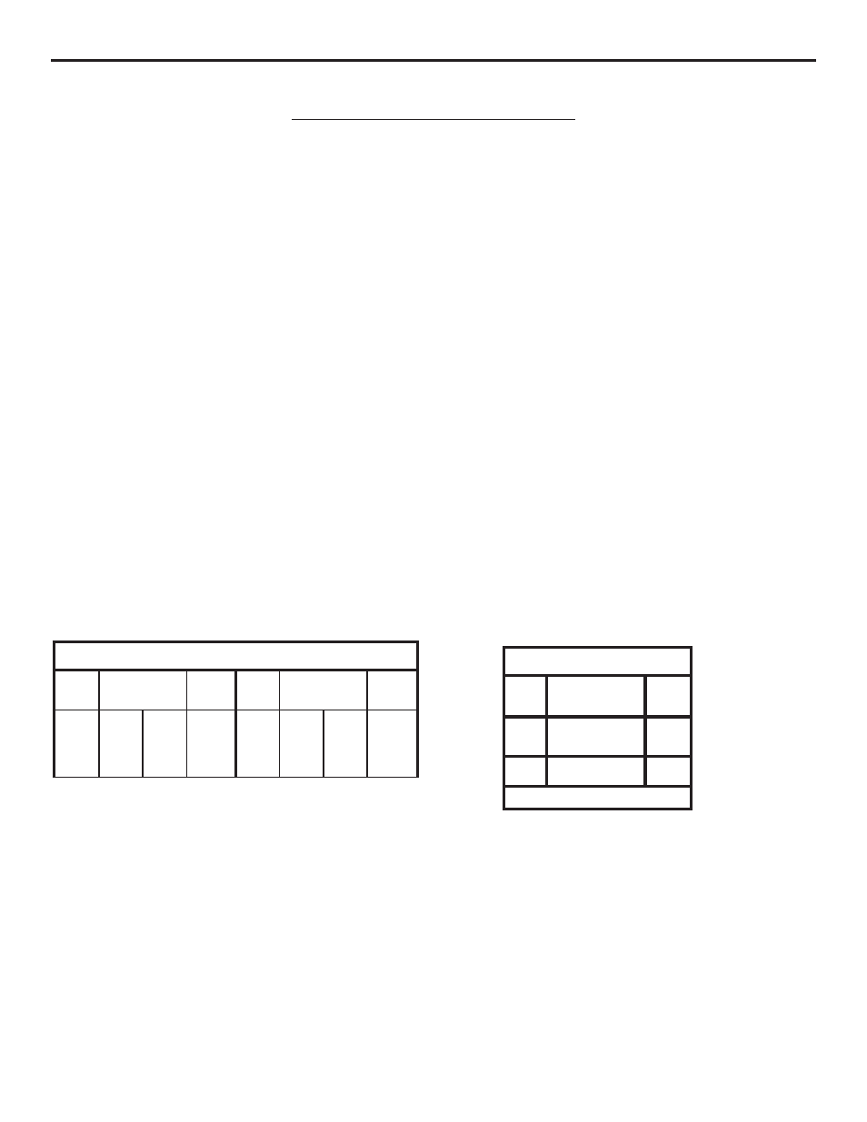
ACCESSORY WIRING
All Models
24VDC
*Over 350 ft. use DC power.
0-2000
14
24VAC
250
350*
14
12
Volts
Maximum
Distance (ft.)
Wire
Gauge