Battery installation, Interconnect wiring diagram, Figure 5 – Kidde RF-SM-ACDC User Manual
Page 9
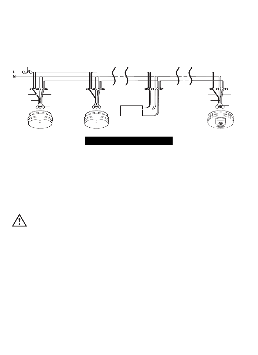
• Figure 5 illustrates interconnection wiring. Improper connection will result in
damage to the alarm, failure to operate, or a shock hazard.
• Make certain alarms are wired to a continuous (non-switched) power line.
NOTE: Use standard UL listed household wire (as required by local codes)
available at all electrical supply stores and most hardware stores.
BATTERY INSTALLATION
CAUTION! THIS UNIT WILL NOT FUNCTION WITHOUT A PROPERLY
INSTALLED BATTERY, AND IS EQUIPPED WITH A BATTERY LOCKOUT
FEATURE WHICH PREVENTS THE BATTERY DOOR FROM CLOSING IF A
BATTERY IS NOT INSTALLED CORRECTLY.
If your unit was supplied with a yellow pull tab, gently pull the tab out to acti-
vate the battery backup once the unit has been connected to AC power and
mounted to the electrical box with the included trim ring. See MOUNTING
INSTRUCTIONS in the following section.
To install a battery for the first time, remove the alarm from the mounting
bracket and open the battery door. Battery installation instructions are provided
on the inside of the battery door. When installing, use the battery to press the
battery reminder finger down into the battery compartment (see figure 6).
FUSE OR CIRCUIT BREAKER
RED
BLACK
WHITE
BLACK
WHITE
RED
CONNECTOR
CONNECTOR
Existing Alarms
Kidde
Relay Module
SM120X
Wireless Alarm
(1 ONLY)
Optional
Accessory
FIGURE 5
INTERCONNECT WIRING DIAGRAM
WIRES ON AC QUICK CONNECTOR MUST BE CONNECTED TO:
Black . . . Hot Side of AC Line
White . . . Neutral Side of AC Line
Red . . . . Interconnect Lines (Red Wires) of Other Units in the Multiple Station Setup