System connections, Caution, Caution regarding placement – Kenwood DP-4090 User Manual
Page 4
DP-5090/4090 (En)
4
System connections
Caution:
Do not plug in the power lead until all connections are com-
pleted.
Malfunction of microcomputer
If operation is not possible or erroneous display appears even
though all connections have been made properly, reset the
microcomputer referring to “In case of difficulty”.
¡
Make connections as shown below.
When connecting the related system components, refer also to the
instruction manuals of the related components.
Caution regarding placement
To maintain proper ventilation, be sure to leave a space around the unit (from the largest outer
dimensions including projections) equal to, or greater than, shown below.
Left and right panels: 10 cm
Rear panel: 10 cm
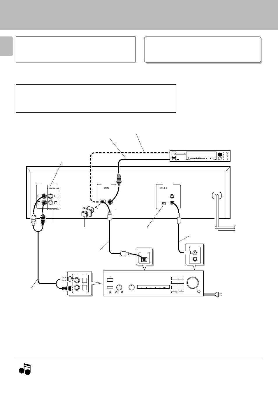
SYSTEM
CONTROL
L
R
CD
L
R
L
R
LINE 1 LINE 2
OUTPUT
DIGITAL
OUTPUT
SYSTEM
CONTROL
OPTICAL COAXIAL
SL16 XS 8
ƒ
AC110-220V
2 3AC220-240V
DIGITAL
INPUT
OPTICAL
TEXT
(DP-5090 only)
LINE 1 and LINE 2 output are the same
pair of signals. Use these jacks to connect
the unit to other system components.
75
Ω
coaxial cable with RCA PIN.
(Commercially-available)
Commercially-available
optical fiber cable
DIGITAL INPUT
(COAXIAL)
(OPTICAL)
Digital component (MD, DAT, etc.)
Commercially-available
optical fiber cable
Remove the protection cap
when using the DIGITAL
OUTPUT (OPTICAL) jack.
Audio cord
SL 16/XS8
switch
6
System control cord
Digital amplifier
(or ordinary amplifier,
␣ ␣ ␣ receiver, etc.)
To wall AC outlet
1. Connect all cords firmly. If connections are loose there could be loss of sound or noise produced.
2. When plugging and unplugging connection cords, be sure to first remove the power cord from the AC outlet. Plugging/unplugging
connection cords without removal of the power cord can cause malfunctions or damage to the unit.
Notes
Notes
(Except for DP-4090)
To AC outlet