Konica Minolta NON-CONTACT 3D DIGITIZER VIVID 9i User Manual
Page 37
35
Field Calibration
2
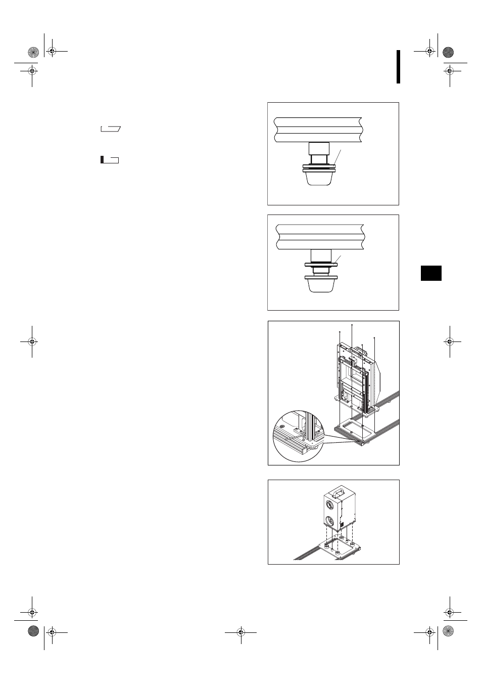
Turn the lock nut counterclockwise to unlock the
rubber foot block.
M
emo
Turn clockwise for lower heights and counterclockwise for
higher heights.
N
ote
Because there is no preventive structure, moving the rub-
ber foot block more than adjustable range may cause the
rubber foot block to fall off. In this case, screw the rubber
foot block onto the stopper unit clockwise.
3
After adjusting the height correctly, move the lock
nut to the stopper unit by turning it clockwise and
lock the rubber foot block.
3
Attach the Unit Attachment Section to the
Field Calibration System Unit Section.
Use the 4 screws and tighten them firmly with the in-
cluded hex wrench.
4
Attach the VIVID 9i Attachment Section to the
main unit.
Make sure the footings at the base of the main unit are
inserted into the 4 footing seats.
Adjust the height
by turning the Rub-
ber foot block.
• The lock nut
moves in the
same height di-
rection as the
rubber foot block.
After adjustment of
the height, move
the lock nut to the
stopper unit by
turning it clockwise
and lock the rub-
ber foot block in
place.
Vivid910-hard-E.book Page 35 Monday, October 18, 2004 3:11 PM