N names of parts and functions, Nnames of parts and functions – Konica Minolta Non-Contact 3D Digitizer Range7 User Manual
Page 9
7
n
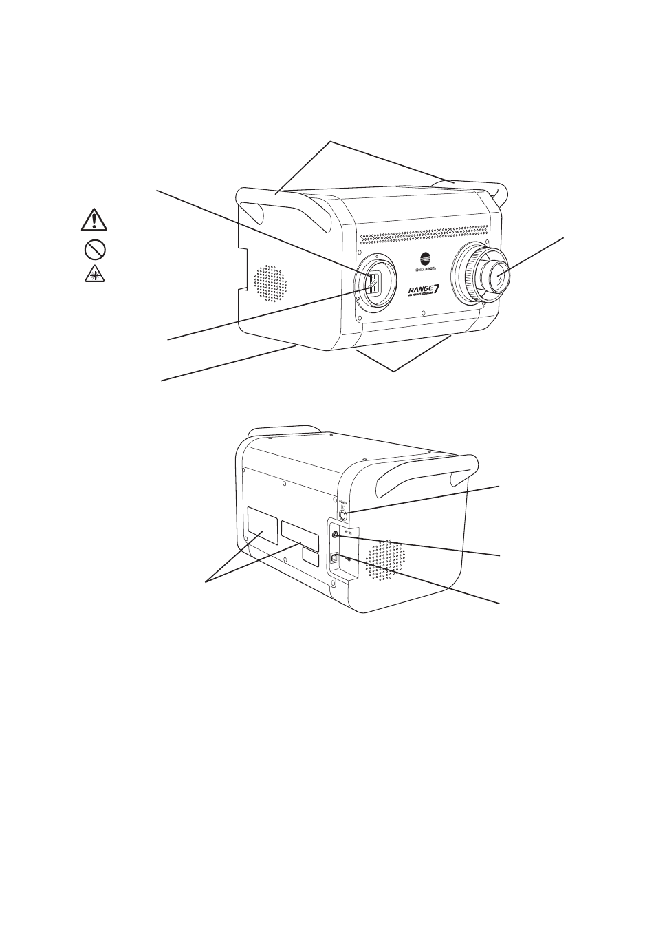
Names of Parts and Functions
1) Carrying handle
Used to lift or carry the RANGE7/5. (Be sure to hold the RANGE7/5 body with both hands.)
2) Light-receiving lens
Exchange the light-receiving lens for an optimum lens (Tele or Wide lens), depending on
the measuring target size and measuring distance.
3) Laser-emitting window
A laser beam is emitted to a measuring target from this window. (Do not stare directly into
the laser beam.)
4) Lens shutter
When the power is switched off, this shutter closes to protect the laser emitting window.
5) Rubber sole
Four rubber soles are attached at the bottom of the RANGE7/5. To install the RANGE7/5
directly on a firm table, use these parts. Also, use the calibration chart set during field
calibration (under standard accessories); or when mounting the RANGE7/5 to the tripod
set, or measuring stand set (under optional accessories), use these parts to set the
RANGE7/5 in place.
6) Platform mounting screw hole Screw holes for fastening the RANGE7/5 to the measuring stand platform or tripod
platform (under optional accessories).
7) Power switch
Turns ON/OFF the RANGE7/5 power supply.
8) AC adaptor terminal
Connect the RANGE7/5 AC adaptor plug to this terminal.
9) USB port
When connecting the RANGE7/5 to a PC, connect the USB cable (standard accessory)
Type B plug.
3) Laser-emitting Window
4) Laser shutter
5) Rubber sole
7) Power switch
8) AC adapter terminal
6) Platform mounting screw hole
WARNING
A laser beam is emitted
from this port.
Do not stare directly into
the laser beam.
1) Carrying handle
2) Light-Receiving Lens
9) USB port (Type B)
Laser Label Indication (page 3)