Chapter 2 - installation – Stellar Industries TELESCOPIC CRANE EC2000 User Manual
Page 7
3
Installation 3
Chapter 2 - Installation
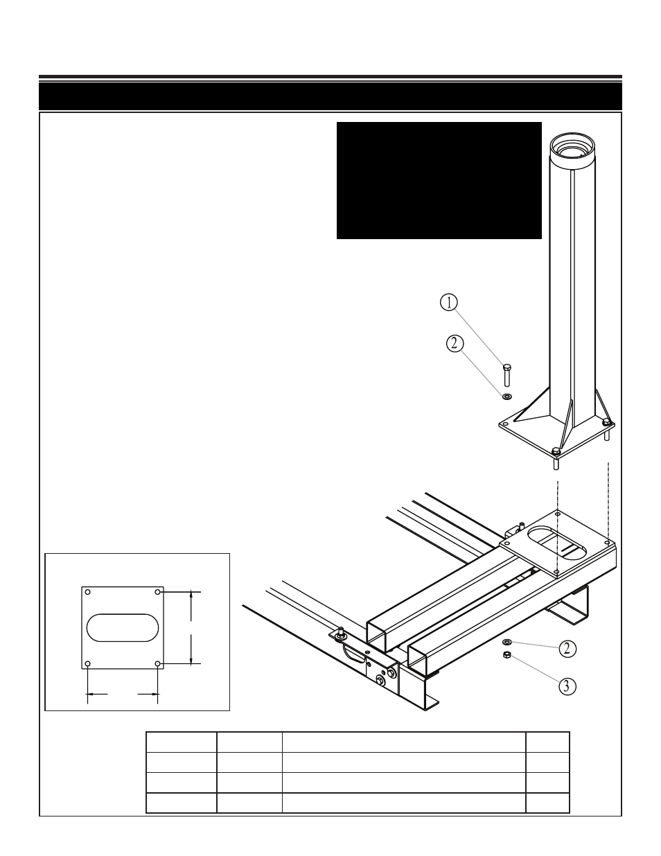
Mounting Hole Diagram
Item No. Part No. Description
Qty.
1
D1034 CAP SCR 0.63-11 X 3.00 HHGR8 ZY
4
2
C5902 WASHER 0.63 FLAT GR8
8
3
2826
NUT 0.63-11 HH NYLOC
4
10.25
10.25
Notice: Read this Page Before Installation of the Crane
Installation Instructions:
Prepare Platform For Crane Installation (Not
Supplied)
1. When designing the platform, maintain a
proper clearance for the crane mount-
ing and operation.
2. The platform must be strong enough to
support the crane and rated load.
3. Platform/crane support minimum require-
ments: Top plate should be made from
0.50” grade 50 plate. The structure
should be supported by 4 x 4 x 3/16 tub-
ing.
Mounting Instructions:
1. Lower the crane onto the mounting plat-
form.
2. Mount the crane using 5/8” grade 8
bolts, flat washers, and nyloc nuts.
3. Connect power (+12V) and ground wires
per winch manufacturer’s specifications.
Power Rotation: Route 4 ga. wires (not
included) from junction box to power
(+12V) and ground. Recommended:
Use solenoid and a toggle switch to
power the crane.
4. Operate the crane for several cycles.
Important: When installing welder units to
the service bodies, it is highly
recommended that a surge protector is
installed on the chassis batteries to protect
the crane radio receiver, wiring and other
electronic devices from an unexpected
electrical spike or surge. Failure to do so
could result in extensive damage to the
service body and crane electrical circuit.