Description of controls & components – Southbend METAL-CUTTING BANDSAW SB1019 User Manual
Page 22
-20-
For Machines Mfg. Since 8/09
Model SB1019
O P E R A T I O N
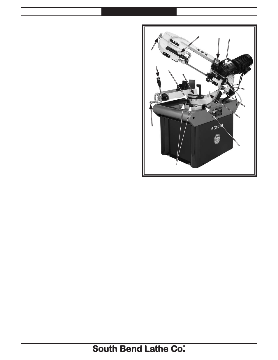
Description of Controls
& Components
Refer to Figure 14 and the following
descriptions to become familiar with the basic
controls and components used to operate this
machine.
A. Blade Tension Knob: Adjusts the position of
the upper blade wheel to apply or release
blade tension.
B. Guide Post Knob: Locks the guide post in the
position set by the operator.
C. ON/OFF Switch: Turns the saw motor ON &
OFF.
D. Speed Selector: Selects one of three blade
speeds.
E. Downfeed Rate Adjust Knob: Controls the
speed at which the blade lowers into the
workpiece.
F. Downfeed Valve: Controls the starting and
stopping of the headstock downfeed.
G. Downfeed Stop Bolt: Adjusts to determine
the absolute bottom limit of blade travel.
H. Headstock 0° Flip Stop: Provides an optional
stop for square cuts.
I. Headstock 45° Stops: Provide stops at 45° to
the left and right for angle cuts.
J. Vise Jaw Handwheel: Controls the vise jaw
movement.
K. Vise Jaw Quick Release Lever: Quickly
opens and closes the vise jaw approximately
1
⁄
16
" for repetitive repositioning/clamping in a
production setting.
L. Headstock Lock Lever: Locks the headstock
at the position set by the operator.
M. Work Stop: Provides an adjustable stop for
cutting multiple workpieces at the same
length.
A
H
I
J
K
L
M
G
F
B
C
D
E
Figure 14. Controls and components.