Appendix c: interface pin outs, Parallel interface – Star Micronics LC-1021 User Manual
Page 68
62
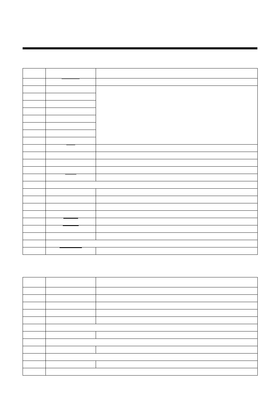
Appendix C: Interface Pin Outs
Parallel Interface
Pin
Name
Function
1
STROBE
Goes low for
≥
0.5
µ
s when active.
2
DATA0
These signals represent information for the 1st through 8th bit of parallel data,
respectively. Each signal is HIGH when data is logical 1, and LOW when logical
0.
3
DATA1
4
DATA2
5
DATA3
6
DATA4
7
DATA5
8
DATA6
9
DATA7
10
ACK
10
µ
s low to acknowledge receipt of data.
11
BUSY
Printer sets line low when ready to receive data.
12
PAPER
High when paper runs out.
13
SELECT
High when printer is on-line.
14
AFXT
Printer ignores this signal
15
Not used.
16
S-GND
Signal ground
17
F-GND
Frame ground
18
+5V
+5V DC output from printer
19 - 30
GND
Twisted pair ground return
31
RESET
Printer is reset when this signal goes low.
32
ERROR
Low when printing cannot continue due to error.
33
EXT GND
External ground
34 - 35
Not used
36
SELECT IN
Printer ignores this signal
Optional Serial Interface (IS-8H192 and SPC-8K)
Pin
Name
Function
1
F-GND
Frame ground
2
TXD
Data from printer
3
RXD
Data to printer
4
RTS
Always space
5
CTS
Space when computer is ready to send data. Printer ignores this signal.
6
Not used.
7
GND
Signal ground
8 - 10
Not used.
11
RCH
Printer sets line to space when ready to receive data. Same signal as Pin 20.
12 - 19
Not used.
20
DTR
Printer sets line to space when ready to receive data.
21 - 25
Not used.