4 drive mounting, Drive mounting, Figure 2 – Seagate Pipeline HD Mini Series SATA ST91603110CS User Manual
Page 28: Attaching sata cabling
18
Pipeline HD Mini Series SATA Product Manual, Rev. E
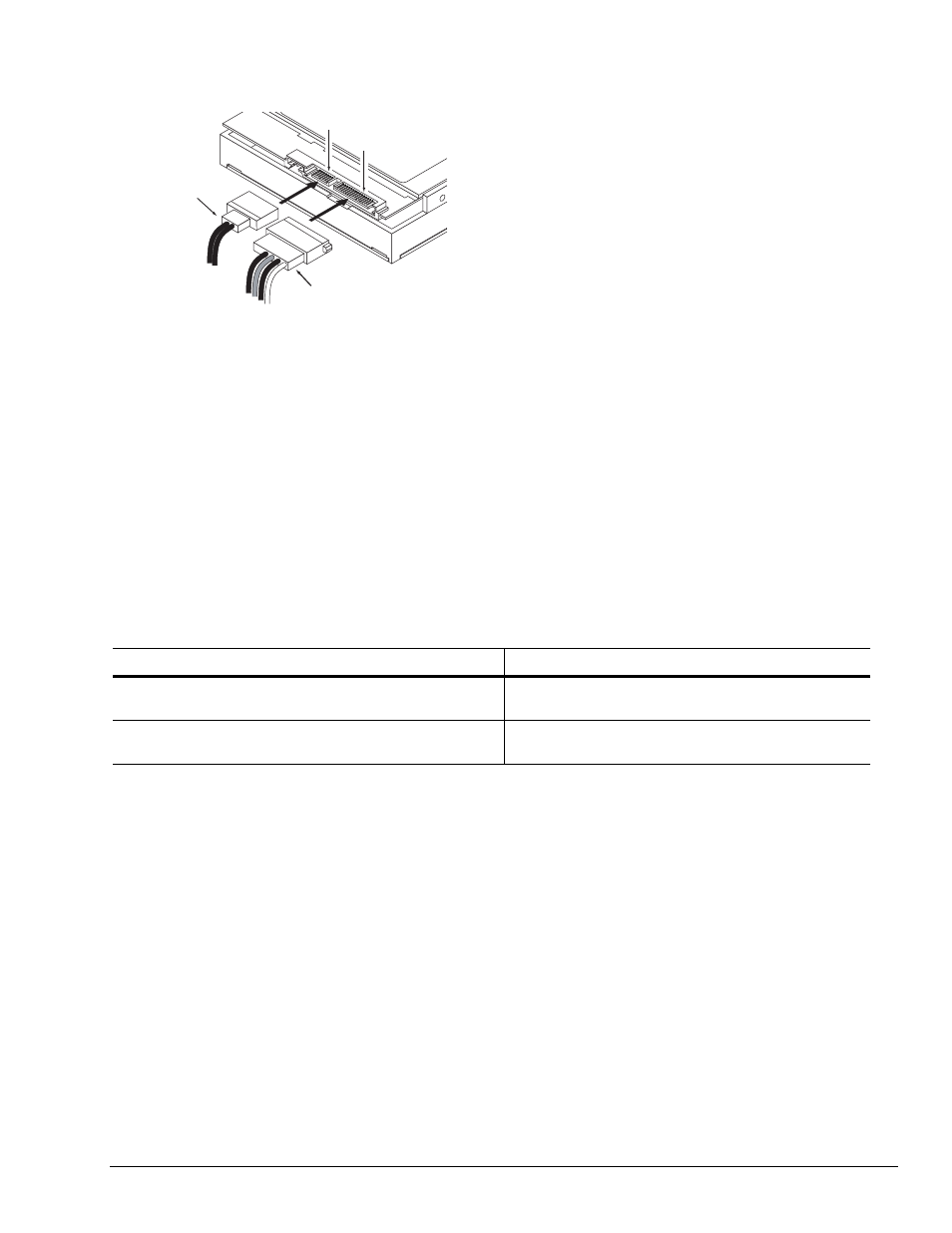
For installations which require cables, you can connect the drive as illustrated in Figure 2.
Figure 2. Attaching SATA cabling
Each cable is keyed to ensure correct orientation.
3.4
Drive mounting
You can mount the drive using four screws in the side-mounting holes or four screws in the bottom-mounting
holes. See Figure 3 for drive mounting dimensions. Follow these important mounting precautions when mounting
the drive:
• Allow a minimum clearance of 0.030 inches (0.76 mm) around the entire perimeter of the drive for cooling.
• Use only M3 UNC mounting screws.
• Do not overtighten the mounting screws. Maximum torque: 4.0 inch-lb. (0.4519 N-m).
• Four (4) threads (0.080 inches, 2.032 mm) minimum screw engagement recommended.
• Avoid excessive drive distortion when mounting. Refer to the following specifications for stiffness/deflection
information:
Top cover stiffness/deflection
Operating with no performance degradation, emitted noise,
mechanical damage, or hard errors
10 mm probe: 1.02kgf or
5 mm probe: 0.92kgf
Non-operating with no hard errors
20 mm probe: 2kgf at any point of top cover
20 mm probe: 15kgf at top cover edges only
ower ca le
inter ace ca le
inter ace connector
ower connector