Installation – Sanyo VDC-M1024V User Manual
Page 4
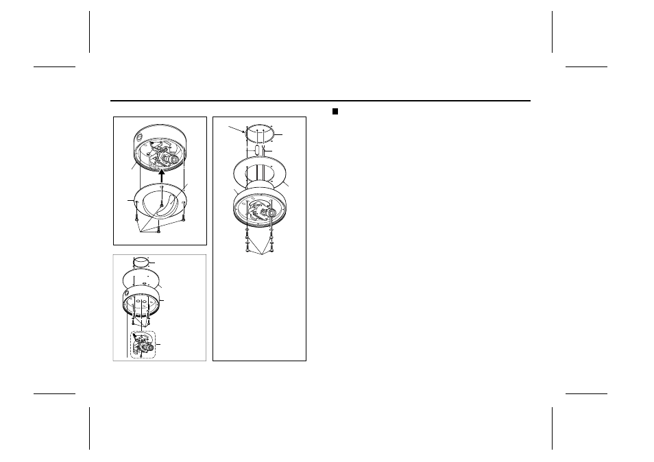
INSTALLATION
Main unit installation
•
Preparation
Make four or more holes in the ceiling or wall for the screws that
are to be used to secure the main unit. If embedding the input
power wire and video out cable, make a hole for these cables to be
passed through also.
•
Main unit installation
1
Use the accessory Allen key to remove the four screws (B) that
are securing the dome assembly (A).
2
Insert the foam gasket (C) in between the housing and the
installation surface.
3
Pass the input power wire (E) and video out cable (D) through
the hole made for that purpose.
4
Align the housing assembly (F) with the screw holes that have
been prepared, and then secure it by tightening the four or
more screws (G) (4 mm diameter screws recommended).
5
Determine the lens position in accordance with the location of
the objects to be viewed, and then tighten it in that position.
(Refer to page 4 for lens adjustment details.)
6
Align the viewing window (H) with the lens position.
7
Return the dome assembly (A) to its original position and secure it.
*
(E) Input power wires: Dual voltage system (12 V DC or 24 V AC 60 Hz)
Mounting Screws (4)
Video Out
Cable
Electrical
Box
Foam
Gasket
Input Power
Wires
Housing
assembly
In-ceiling Type
Housing
assembly
Security
Screws (4)
Dome
assembly
Viewing
Window
Dome assembly installation
Camera/VRB
assembly
Surface Type
Electrical Box
Foam Gasket
Housing
assembly
Mounting Screws (4)
(A)
(B)
(C)
(E)
(D)
(F)
(H)
(G)
72 mm
φ
L5QA2/US,US2, L5QB2/US, US2, L7QA2/US, US2 GB 2002, 4, 24
English
3