Sony MP595 User Manual
Page 26
AirLink MP595 / MP595W Modem User Guide
20
2130795
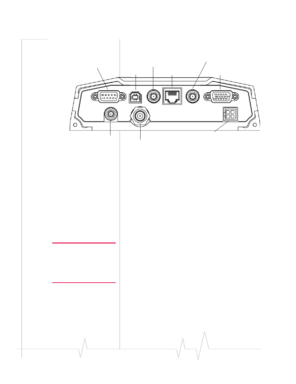
Connector panel
The MP 595 modem has the following connectors:
Figure 3-2: MP 595 modem rear connectors
GPS and I/O options
The MP modem provides support for GPS (Global Positioning
System) and for attaching input/output devices.
GPS. If you plan to use the MP modem’s built‐in GPS module,
you must connect a GPS antenna using an antenna cable, or
use a combination antenna that can connect to both the GPS
and Main RF connectors on the MP modem housing.
Other I/O devices. Other devices, such as panic buttons,
sensors, or gauges may also be installed with the MP modem
and connected with an I/O cable to the I/O port. (See “I/O port
connections” on page 31.)
Overview of installation steps
Note: Electrical installations are
potentially dangerous and
should be performed by
personnel thoroughly trained in
safe electrical wiring procedures
for vehicles.
The installation process for the MP modem varies depending
on how you plan to use it, where it best fits, and which of its
features you plan to use. The main steps are:
1.
Mount the MP modem.
2.
Mount the antennas and connect the cables.
·
Main RF antenna and cable
·
Additional RF antenna and cable, if you plan to use
receive diversity.
·
GPS antenna and cable, if you plan to use GPS
·
WAP antenna and cable (MP 595W only)
3.
Connect the power harness.
I/O connector (DB15HD)
Ethernet
GPS antenna (female SMA)
RS-232 serial (female DB9)
USB (Type B)
Main RF antenna (female TNC)
Power harness (Molex connector)
Diversity antenna (SMA)
Power
I/O
Ethernet Host
GPS
USB Host
Serial Host
Diversity
Main RF
WAP
(MP595 only)
WAP antenna for wireless
access point
For MP 595W only -
SMA connector