Maintenance (continued) – Shindaiwa Articulated Hedge AHS254 User Manual
Page 19
19
CAUTIOn!
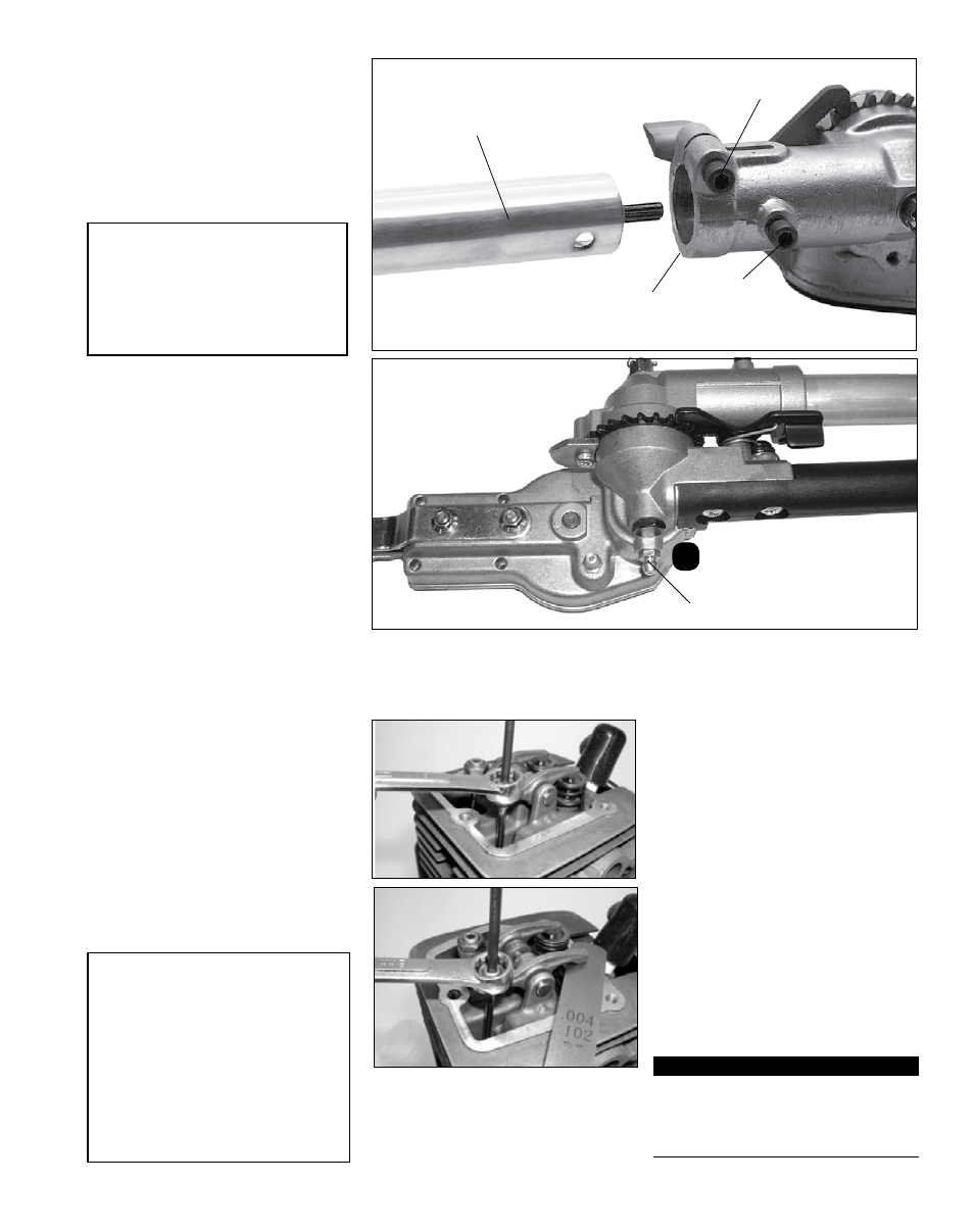
Do not remove the D-shaped shim
washer from the gearcase clamp!
The shim washer prevents damage
from overtightening the tube clamp
bolt.
Gearcase lubrication
To perform this operation, first remove
the gearcase from the outer tube as
follows:
1. Loosen the gearcase clamp bolt.
2. Remove the index bolt from the
gearcase.
Lubricate cutter assembly and gearcase
Gearcase
grease fitting
B
Outer tube
Gearcase
Gearcase Clamp bolt
Index bolt
Remove the outer tube from the gearcase
Gearcase lubrication
3. Slide the gearcase out of the tube.
Using a grease gun, pump lithium-
base grease (about 10 grams) into
the grease fitting (B) on the gearcase
until you see old grease being purged
from the gearcase. Purged grease will
be visible in the outer tube cavity.
4. Clean up excess grease, then reas-
semble the gearcase onto the outer
tube. Make sure the index bolt fits
into the hole on the outer tube.
Securely tighten both bolts.
Maintenance (continued)
IMPORTAnT!
If a new gasket is not available and/
or the old gasket is not damaged, the
old gasket may be reused. Never use
cracked or damaged gaskets!
4. Turn adjustment screw (clockwise =
tighter, counter-clockwise = looser)
until feeler gauge is almost snug.
Back off just enough to allow gauge
to slip out with limited resistance.
5. While holding the adjustment screw
in place with the Allen driver, tighten
the locknut with a wrench.
6. Turn engine over several times,
and return to TDC-compression.
Recheck with proper feeler gauge to
make sure clearance adjustment did
not change as a result of tightening
the locknut. Readjust as necessary.
7. Replace rocker arm cover gasket
to assure proper sealing and install
cover.
135-Hour Maintenance
■
Combustion chamber should be
decarbonized, and the valve clear-
ance should be adjusted. It is highly
recommended that this is done
by a Shindaiwa-trained service
technician.
1. Remove cylinder cover, rocker arm
cover, and spark plug. Rotate the
crankshaft while observing the pis-
ton through the spark plug opening.
When the piston is at the top of the
compression stroke (TDC), the valves
can be adjusted.
2. Loosen adjuster locknut so that the
2.5 mm Allen socket head adjust-
ment screw can turn freely.
3. Insert 0.10 mm feeler gauge between
valve stem tip and rocker arm.
CAUTIOn!
■
Performing a valve adjustment
incorrectly may cause hard
starting and/or can damage the
engine.
■
If you are unfamiliar with this
engine or uncomfortable with
this procedure, consult with an
authorized Shindaiwa servicing
dealer.
Valve Adjustment