Enforcer – Controlled Products Systems Group SK-1123-FQ User Manual
Page 7
ENFORCER
F
LUSH
-M
OUNT
O
UTDOOR
A
CCESS
K
EYPAD
ENFORCER
F
LUSH
-M
OUNT
O
UTDOOR
A
CCESS
K
EYPAD
SECO-LARM U.S.A., Inc.
SECO-LARM U.S.A., Inc.
®
®
N.O. Egress button
(Open door from inside)
Note: Additional egress buttons
can be connected in parallel.
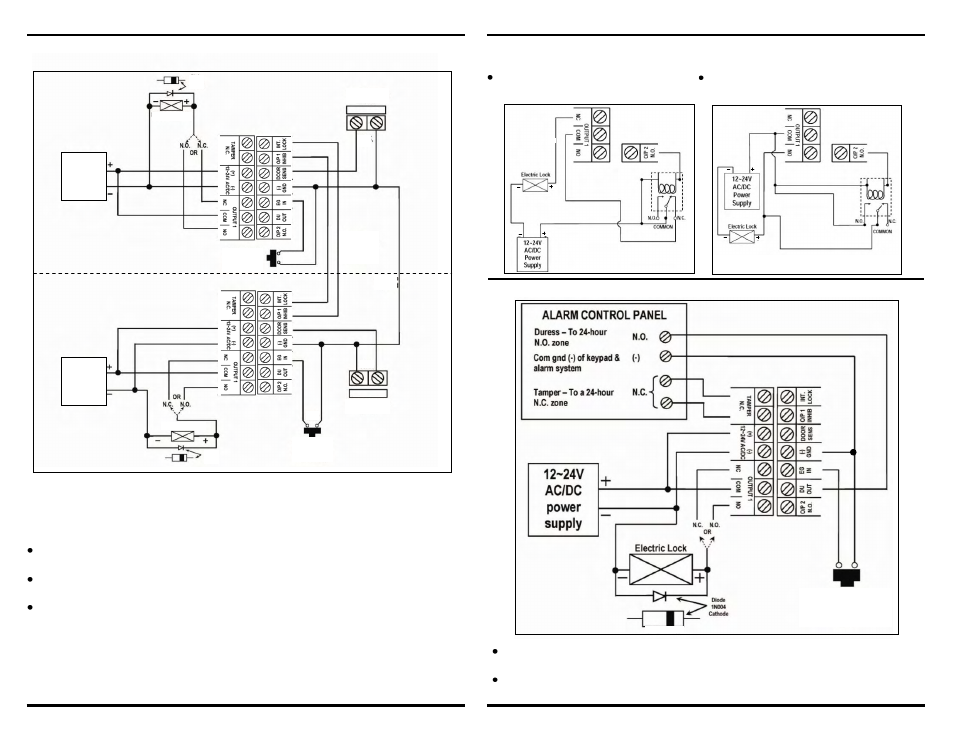
Connect the duress output to a 24-hour N.O. zone and the tamper output to a 24-hour N.C.
zone on the alarm control panel.
The keypad’s terminal ground (-) connects to the ground (-) wire of the alarm control panel to
enable the two to work together.
5. Door-Hold-Open Mode
W
IRING
Example Wiring, 2 Keypads with Mantrap Interlock
Mantrap (Interlock) – Each keypad can be used as a stand-alone keypad. The mantrap feature is
for a protected area with two doors to ensure only one door can be opened at a time. With the
mantrap feature enabled, when a user opens one door either by entering a code or with a request-
to-exit button, a signal is sent to the second keypad to disable it, thereby preventing access through
the second door until the first door is closed.
Use an N.C. magnetic contact or some other N.C. device to detect whether a door is opened or
closed. Do this for the two doors being protected.
Combine this wiring diagram with the diagram on page 7 if connection to an alarm control panel
is required.
To use the mantrap feature:
o
Use either the keypad from outside or the egress button from inside the protected premises
to open one of the two doors.
o
While the first door is opened, the first keypad sends a signal to the second keypad to
prevent the second door from being opened.
o
Once the first door is closed, both doors are ready to open again.
DOOR #1
Page 10
Page 7
DOOR #2
Diode
1N4004
Cathode
Diode
1N4004
Cathode
Egress button
(Open door #2
from inside)
Door #2 sensing
SM-200
N.C.
Common
ground
Crosswire
connection for
interlock
functions
N.C.
Door #2 sensing
SM-200
Egress button
(Open door #2
from inside)
12~24V
AC/DC
power
supply
12~24V
AC/DC
power
supply
N.O.
N.O.
Electric
Lock #1
Electric Lock #2
W
IRING
–
Example Wiring, with Connection to Lock Device
For N.C. locking devices: Connect a relay
to output 2 in series with the locking device.
For N.O. locking devices: Connect a relay to
output 2 in parallel with the locking device.
(For DC use only)