Adjustments, Assembly (continued) – Shindaiwa 81704 User Manual
Page 7
7
3/16-1/4 inch
(4-6 mm)
Throttle Free
Play
Adjust Throttle Lever Free Play
1. Remove the air cleaner cover by loosen-
ing the two thumbscrews. See Figure 7.
2. Loosen the lock nut on the cable ad-
juster. See Figure 8.
Adjustments
Figure 7
The throttle lever free play should be ap-
proximately 3/16-1/4 inch (4-6 mm). See
Figure 6. Make sure that the throttle lever
operates smoothly without binding. If it
becomes necessary to adjust the lever free
play, follow the procedures and illustrations
that follow.
Figure 6
3. Turn the cable adjuster in or out as
required to obtain proper free play
3/16-1/4 inch (4-6 mm). See Figure 8.
4. Tighten the lock nut.
5. Reinstall the air cleaner cover.
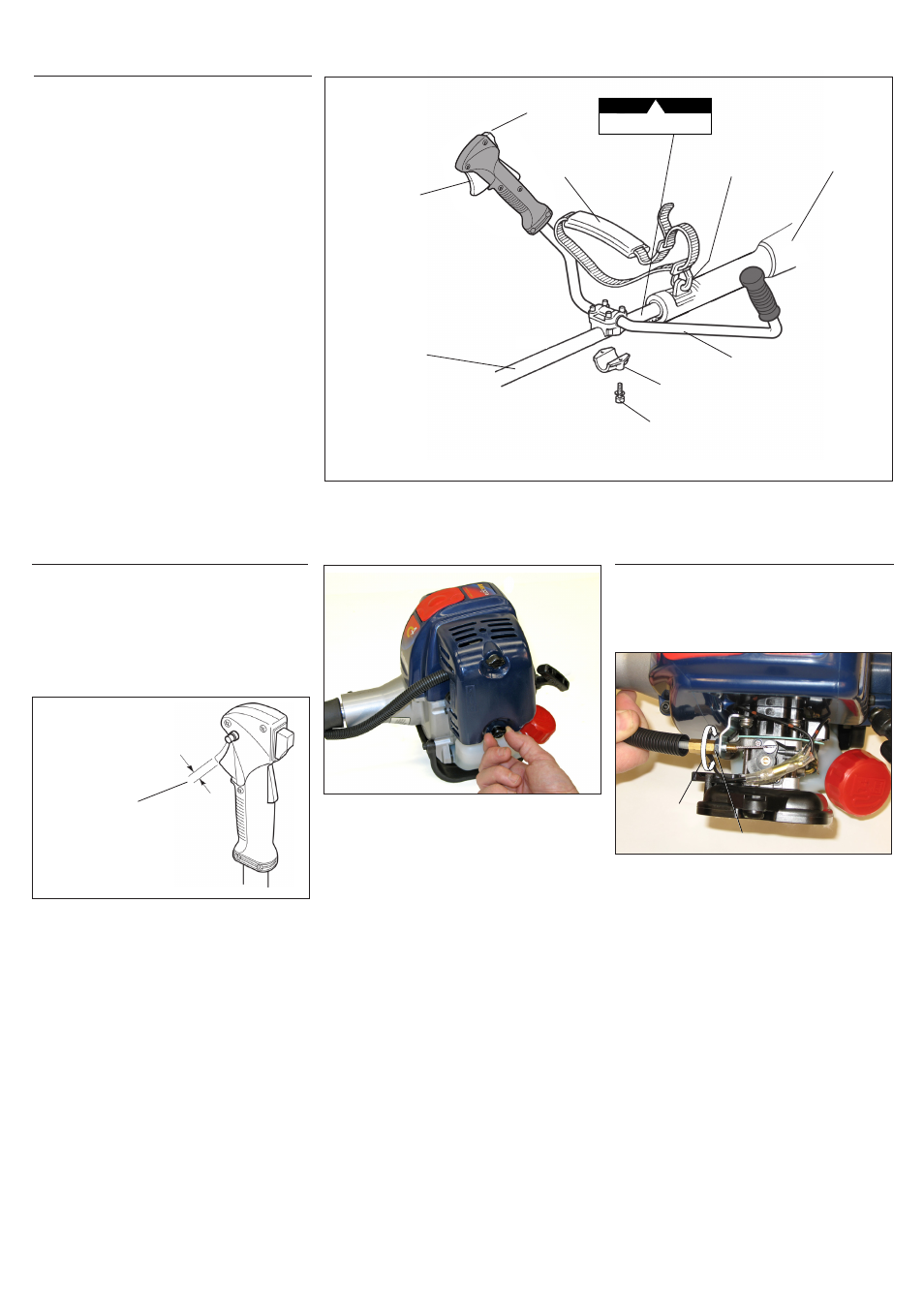
Install the handlebar:
1. Use the 4 mm hex wrench to remove
the lower cap retaining screws from the
handlebar bracket. Remove the cap from
the bracket. See Figure 5.
2. Position the handle on the outer tube
forward of Handle Positioning Label
as shown in Figure 5. Reassemble the
lower cap to the handlebar bracket in
the reverse order of disassembly.
3. Locate the handle in the best position for
operator comfort.
4. Firmly tighten both lower cap retaining
screws.
5. Install the protector sleeve on the outer
tube. See Figure 5.
Handle Bar C2510
Assembly (Continued)
Cable
Adjuster
Figure 8
Lock Nut
Outer Tube
Mounting Bracket
Socket-Head
Cap Screw
Handlebar
Protector Sleeve
Ignition Switch
Throttle
Trigger
Hanger
Shoulder Strap
Handle Positioning Label
POSITION HANDLE
FORWARD OF THIS LINE
C2510
Figure 5