Db500a rear panel, Db500a layout, English – Samson dB500a User Manual
Page 8: Db500a rear panel layout, Db500a
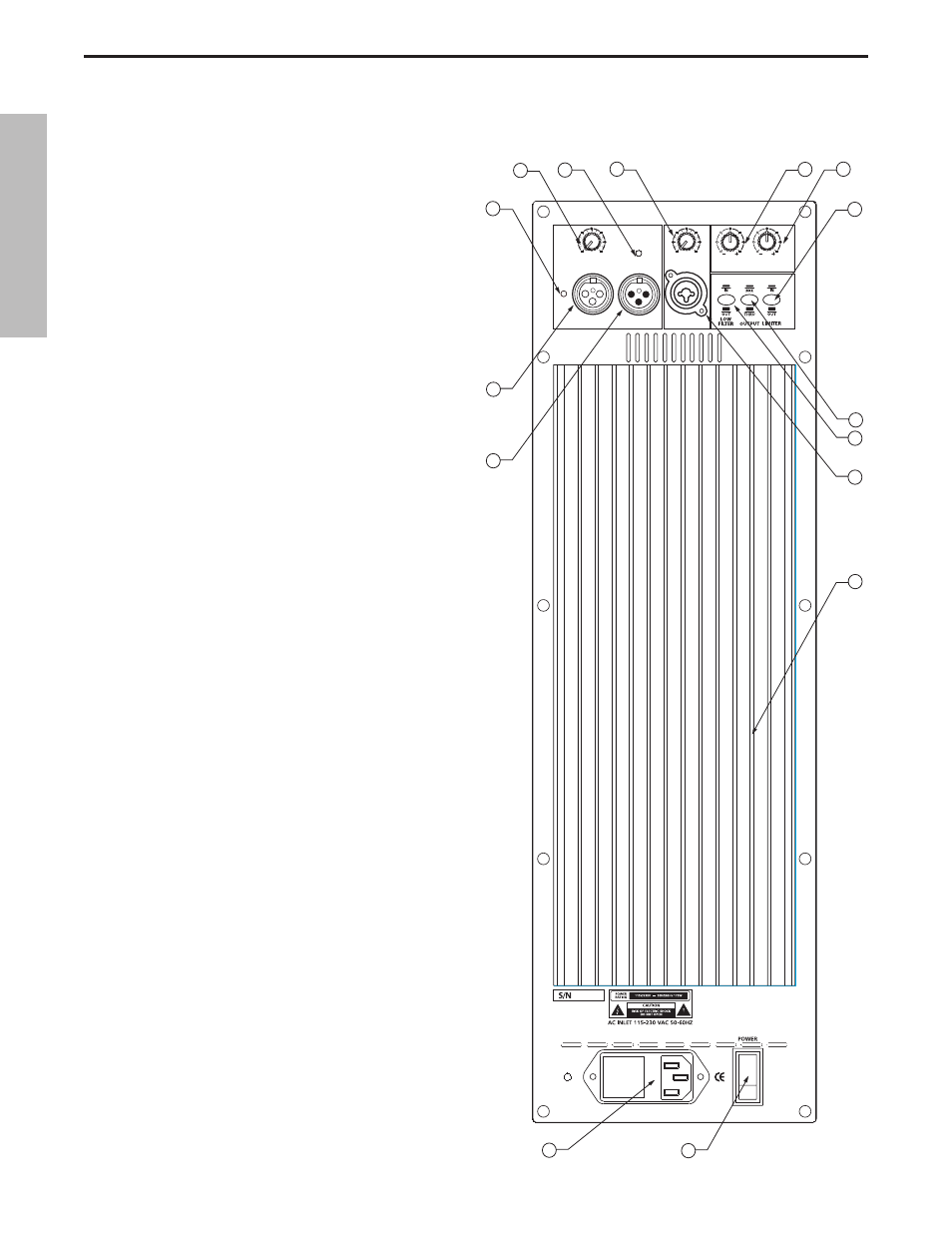
dB500a REAR PANEL
1
MIC LEVEL – Used to adjust the volume of the micro-
phone input.
2
AMP / CLIP LED - Dual color LED lights Green when
amp is active, flashes Red when the amp is clipped or
stays Red indicating the amplifier is in protect mode.
3
LINE LEVEL – Used to control the level of the line
input.
4
LOW FREQUENCY - Controls the low band
of the Channel Equalizer, +/- 12 dB at 100Hz.
5
HIGH FREQUENCY - Controls the high band of the
Channel Equalizer, +/- 12 dB at 10kHz.
6
LIMITER SWITCH - Used to engage the dB500a’s
Optimax dynamics processing. A red LED will illumi-
nate indicating the Optimax is on.
7
OUTPUT SWITCH - This switch is used to select the
signal that is sent to the Line Output. When the switch
is in the up position, the signal on the Line Output is
exactly the same as the signal on the Input. When the
switch is in the down position the Line Output carries
the MIX of the Mic and Line Inputs, as well as the High
and Low Equalizer and Low Filter.
8
dB500a Layout
PROTECTION
DESIGNED AND ENGINEERED IN THE UNITED STATES BY SAMSON TECHNOLOGIES
www.samsontech.com
dB500A
MADE IN CHIN
A
SAMSON
MIC LEVEL
0
10
AMP / CLIP
LINE OUTPUT
MIC INPUT
LINE INPUT
LINE LEVEL
0
10
12
12
12
12
8
8 8
8
4
4
4
4
EQUALIZER
LOW 100Hz
HIGH 10KHz
P E A K
1
2
3
4
5
6
8
9
11
13
14
10
12
15
7
dB500a Rear Panel Layout
ENGLISH
4