SIIG Transport GX21 B5350 User Manual
Page 19
2.2 Installing motherboard components
Chapter 2: Setting up
13
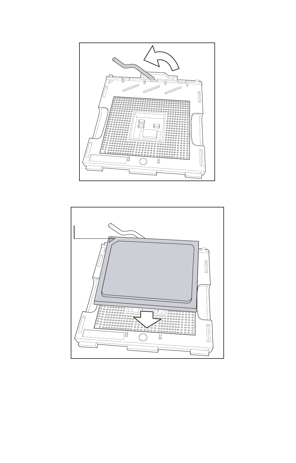
4. Lift the CPU locking lever as shown below.
5. Place the CPU in the CPU socket, ensuring that pin 1 is
located as shown in the following illustration.
6. Press the CPU locking lever back down to secure the
CPU in the socket.
7. Repeat steps three to six for the second CPU.
8. Apply thermal grease to the top of the CPUs and place
the CPU heatsinks on the CPUs.
pin 1
See also other documents in the category SIIG Hardware:
- Network Card (6 pages)
- 04-0444A (8 pages)
- 5.1 (20 pages)
- ID-SC0711-S1 (24 pages)
- RS-232 (12 pages)
- 04-0625A (8 pages)
- FIERY EX2101 (8 pages)
- SATA II-150 (16 pages)
- II-150 (12 pages)
- 04-0288E (12 pages)
- 04-0629A (12 pages)
- 04-0192A (4 pages)
- Network Device EVTEK-5103 (2 pages)
- 04-0417C (12 pages)
- FREEFLOW 701P48438 (20 pages)
- CYBER 2S1P (12 pages)
- PCI 2S (10 pages)
- 133 (12 pages)
- 7.1 (12 pages)
- 04-0631A (20 pages)
- 5090S (12 pages)
- 4110 (8 pages)
- FIERY 700 (8 pages)
- 04-0265F (16 pages)
- 04-0205F (8 pages)
- 5052 (8 pages)
- 700 (12 pages)
- 04-0418A (20 pages)
- 04-0322C (16 pages)
- PCI 4S (10 pages)
- 04-0343C (12 pages)
- UltraATA 133 (26 pages)
- I/O Expander 2S (12 pages)
- 04-0725A (12 pages)
- 04-0207A (8 pages)
- 104-0561C (12 pages)
- 04-0373C (36 pages)
- CYBER 1S1P PCI (12 pages)
- 04-0589A (8 pages)
- 04-0263E (8 pages)
- 4590 (8 pages)
- 04-0341D (12 pages)
- 04-0322B (12 pages)
- Computer Drive (8 pages)