Smart Technologies X-Port 20 Switch (XP20-2000i-B) User Manual
Page 6
2
Installing an X-Port 20 Switch in a 2000i
99-00539-00 Rev B0
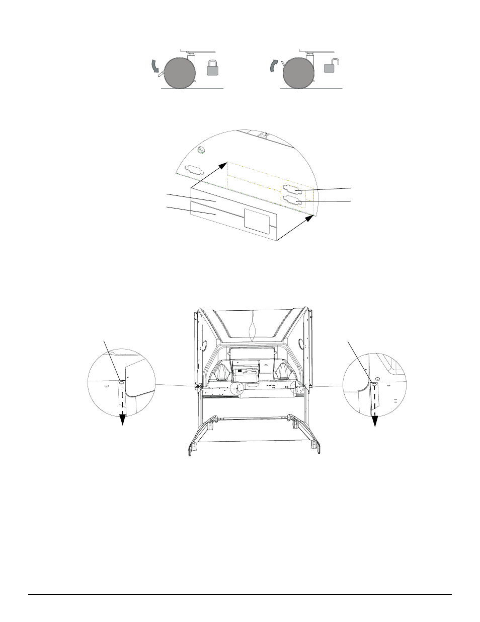
2.
Make sure the casters are locked and all four anti-tip feet are extended.
3.
Remove the stickers covering the lower DB9 opening and the upper HD15 opening. Place the supplied serial (computer) label over
the lower opening and the supplied video label over the upper opening, as illustrated below.
Replacing the Labels
4.
While propping up the electronics tray with one hand (so it doesn’t fall suddenly), remove the two button head hex screws on either
side of the tray using a 5/32" hex key (provided in the accessory kit for the 2000i). Put the hex screws in a safe place as you’ll need
them to secure the electronics tray at the end of this installation.
Location of Button Head Screws
Video Label
Serial (Computer) Label
Upper HD15 Opening
Lower DB9 (Computer)
Opening
Button Head Screw
Button Head Screw
Rear View of 2000i with
Back Legs Removed for Clarity