4 digital positioner 23, 1 calibrating the positioner 23, 4 digital positioner – Samson Electri Actuator Type 3374 EB 8331-1 EN User Manual
Page 23: 1 calibrating the positioner
5.4 Digital positioner
To install a positioner, a corresponding ac-
tuator PCB and the TROVIS-VIEW software
as well as a connecting cable (1400-7699)
are necessary.
Note: Actuators with a digital positioner
cannot be equipped with resistance transmit-
ters.
1. Remove the fastening screws. Push the
actuator board (1) from its guiding to
the right. Take out the board and re-
place it with a board with positioner.
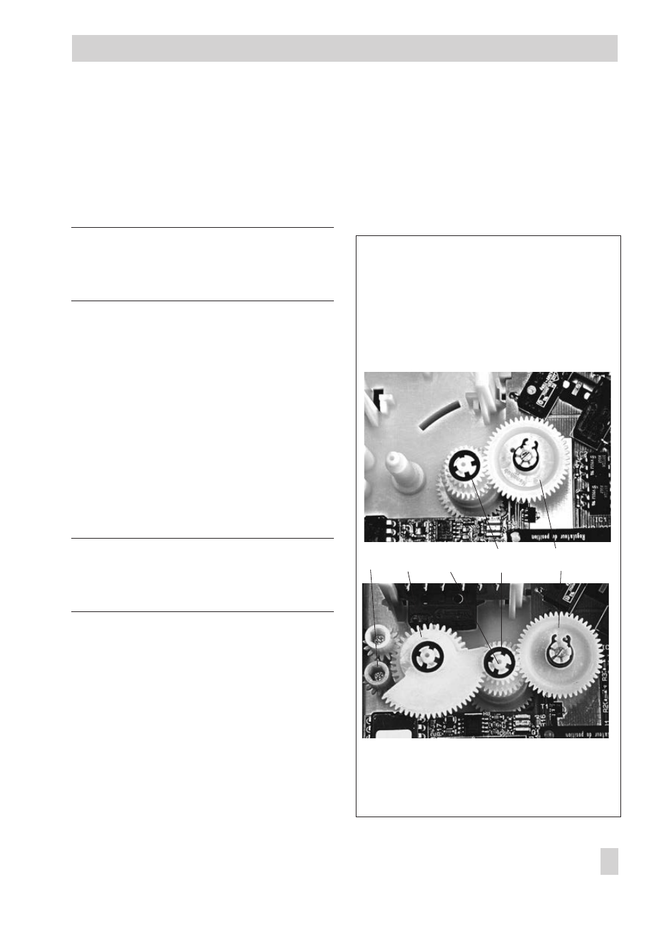
2. Clip the spindle gear (2) onto the sleeve
(3) as illustrated at the top of Fig. 12
(top). Make sure the lateral latch is prop-
erly engaged in the groove of the sleeve.
3. Plug intermediate gear (5) onto the spin-
dle (4). Place the serrated ring (10) on
top and push it down as far as it will go.
Note: At this point, follow the instructions
described in section 5.1.2 on page 18 when
a new intermediate plate (index 6) is used.
4. The gear (12) on the feedback potenti-
ometer, which is equipped with a retain-
ing ring, must be put onto its shaft corre-
sponding with the rated travel of the
valve. The rated travel inscription
'Nennhub 15' or B (on the upper side
with the retaining ring) or 'Nennhub 30'
or A (lower side) must be legible from
above (also see Figs. 5 and 6).
5. Push the actuator board (1) back into its
guiding. Make sure that the gears are
properly engaged. Fasten the board us-
ing screws.
5.4.1 Calibrating the positioner
EB 8331-1 EN
23
Retrofitting additional electrical equipment
Fig. 12 · Version with positioner
without (top) and with (bottom) limit contacts
5
Intermediate gear
6
Contact cam
7
Cam bracket
8
Adjustment gears
10 Serrated ring
12 Gear feedback potentiometer
8
7
5
10
12