Sears 247.88852 User Manual
Page 22
22
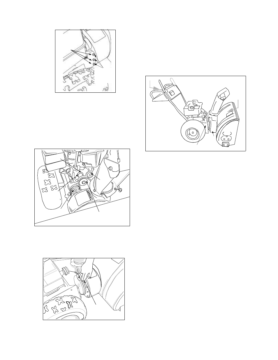
Figure 25
•
Standing in the operating position, lift up on the
handles and pull the frame assembly rearward.
The frame and the housing will separate, and
the rear auger belt will come off the pulley.
Maintain control of the frame assembly while
pulling it.
•
Remove the two belts from the two engine
pulleys. For location of the pulleys, see Figure 26.
Figure 26
•
To remove the front auger drive belt, push the
idler pulley to the left. The belt brake should
move outward. See Figure 27. Lift the front
auger drive belt from the front auger pulley.
Figure 27
Hex
Nut,
Washer
Align studs
for
reassembly
Front Engine
Pulley
Drive
Belt
Idler Pulley
Rear
Engine
Pulley
Auger
Belt
Push auger
idler pulley
•
Place new belts on the two auger pulleys making
sure that the front auger belt is under the belt
brake. Route belts under and to the left of the flat
idler pulley. Hold the belts upward in this
position.
•
While lifting up on the handles, bring the frame
assembly close to the auger housing, and place
the two belts on the front and rear engine
pulleys. See Figure 28.
Figure 28
•
Level the frame assembly and tip the auger
housing forward to align studs with the
corresponding holes on both sides of the frame
assembly. See Figure 25 . Push the frame
assembly fully on to the studs.
NOTE: Use care to avoid pinching the control cable.
•
From the frame assembly side, insert six lock
washers and hex nuts on to the studs . These
pieces of hardware were removed earlier. See
Figure 25. Tighten the nuts securely.
•
Reinstall the belt cover onfront of the engine with
the two self-tapping screws and flat washers.
•
Reattach the chute crank to the chute assembly
with the hairpin clip and flat washer.
NOTE: Make sure that the auger cable is routed in
front of the belt.
Drive Belt
•
Check drive belt every 50 hours of operation for
wear and tear.
•
Drain the gasoline from the snow thrower, or
place a piece of plastic under the gas cap.
•
Remove the plastic belt cover on the front of the
engine by removing the two self-tapping screws.
•
Tip the snow thrower up and forward, so that it
rests on the housing.
•
Remove six self-tapping screws from frame cover
underneath the snow thrower. See Figure 29.
PUSH
PUSH
Frame Assembly
Auger
Housing