1 covered signals – Seagate Ultra 160 User Manual
Page 169
Parallel SCSI Interface Product Manual, Rev. A
155
8.3.2.1
Covered signals
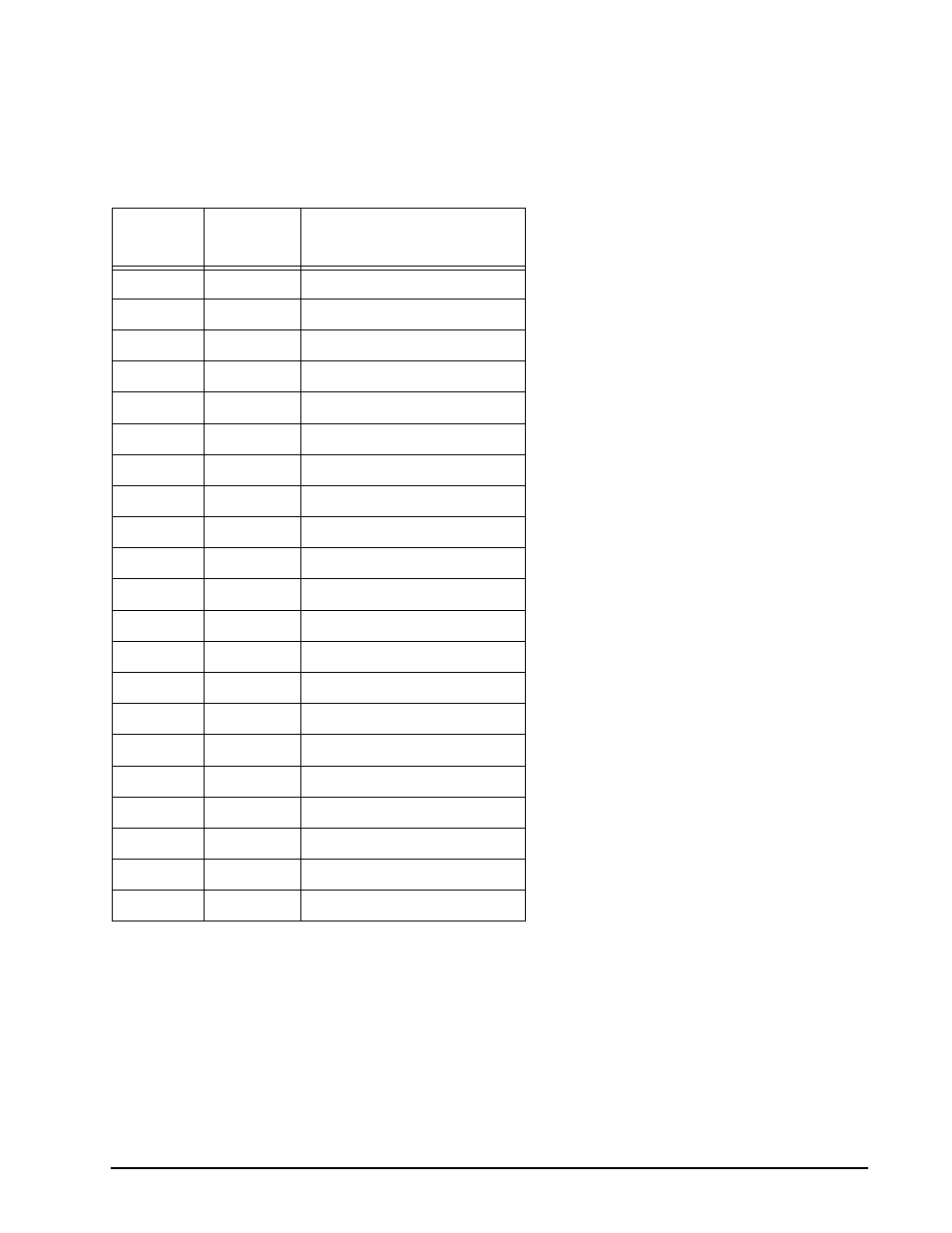
Table 67 defines the signals to be covered by the protection code and their bit locations in the 21-bit code
word. When a SCSI device receives an information byte, it also latches the state of the other SCSI signals and
values noted in Table 67.
Table 67:
Signals to be covered by the protection code and their bit locations
a. DB(8) and DB(9) are reserved for future use. These signals are negated by the transmitting SCSI device
and are ignored by the receiving SCSI device. Both the transmitter and receiver encode these signals in
the protection code.
b. For calculation purposes these signals are zero. However, these virtual signals could be used for other
functions in a future standard.
The Sequence IDs are encoded in the protection code. A sequence of consecutive information transfers during
a Message, Command, or STATUS phase is a run. The Sequence ID increments during a run. A new run
begins on every phase change or on each Message Out retry.
Code
word
location
SCSI
signal
Meaning
0
DB(0)
Data bit 0 of the information byte
1
DB(1)
Data bit 1 of the information byte
2
DB(2)
Data bit 2 of the information byte
3
DB(3)
Data bit 3 of the information byte
4
DB(4)
Data bit 4 of the information byte
5
DB(5)
Data bit 5 of the information byte
6
DB(6)
Data bit 6 of the information byte
7
DB(7)
Data bit 7 of the information byte
8
DB(8)
Reserved [a]
9
DB(9)
Reserved [a]
10
RSVD
Reserved [b]
11
RSVD
Reserved [b]
12
RSVD
Reserved [b]
13
Seq ID 0
Sequence ID bit 0
14
Seq ID 1
Sequence ID bit 1
15
DB(10)
Redundant bit 0 of the code word
16
DB(11)
Redundant bit 1 of the code word
17
DB(12
Redundant bit 2 of the code word
18
DB(13)
Redundant bit 3 of the code word
19
DB(14)
Redundant bit 4 of the code word
20
DB(15)
Redundant bit 5 of the code word