Snapper 1602 User Manual
Page 2
PACKING
The 4 and 6 H.P.
are delivered
complete in their separate cartons. The carton con-
tains:
2
1 Frame, Rotor, Engine and Wheel Assembly
Assembly
1 Spout Adjusting Rod
2 Skid Shoes
1 Bag of Hardware
Should shortages of any of the above items
occur, advise by stating packers number listed on
the green packing
number of Sno-Away,
part number and description of items missing.
ASSEMBLY
1. Fasten the handle assembly to the mount-
ing brackets as shown at
Figure 1, using the (4)
capscrews,
plain washers,
lockwashers and
hex nuts.
2. The throttle
assembly is coiled around
the engine
shipping purposes. Uncoil the cable
and attach ‘to the housing
using the (2)
32”
self-tapping screws. The cable is held in
place by the clamp on the lower portion of the
right handle as shown at
Figure 1.
Figure 1.
Figure 2.
3. Insert the lower end of transmission shift
rod through the hole in the shift lever and fasten in
place with a cotter pin as shown in Figure 1.
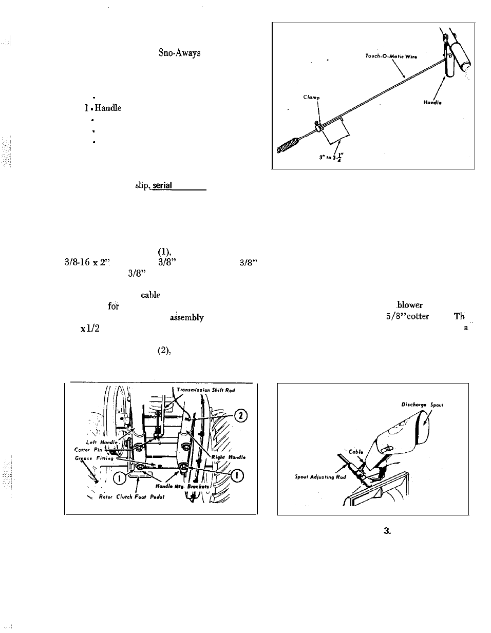
4. Insert the Touch-0-Matic extension wire
through the wire clamp. For proper belt tension,
adjust as shown in Figure 2.
5. Attach the spout control cable as shown in
Figure 3. Insert the lower end of the spout control
rod in the nylon bearing on the
housing and
hold in place with (2)3/32x
pins.
spout control rod support bracket is mounted in
reverse position for shipping purposes. Detach and
mount as shown in Figure 4. Tighten clamp as nec-
essary to hold spout in desired position.
Figure