Integrated model 700br, Planning information – Sub-Zero 700BR User Manual
Page 4
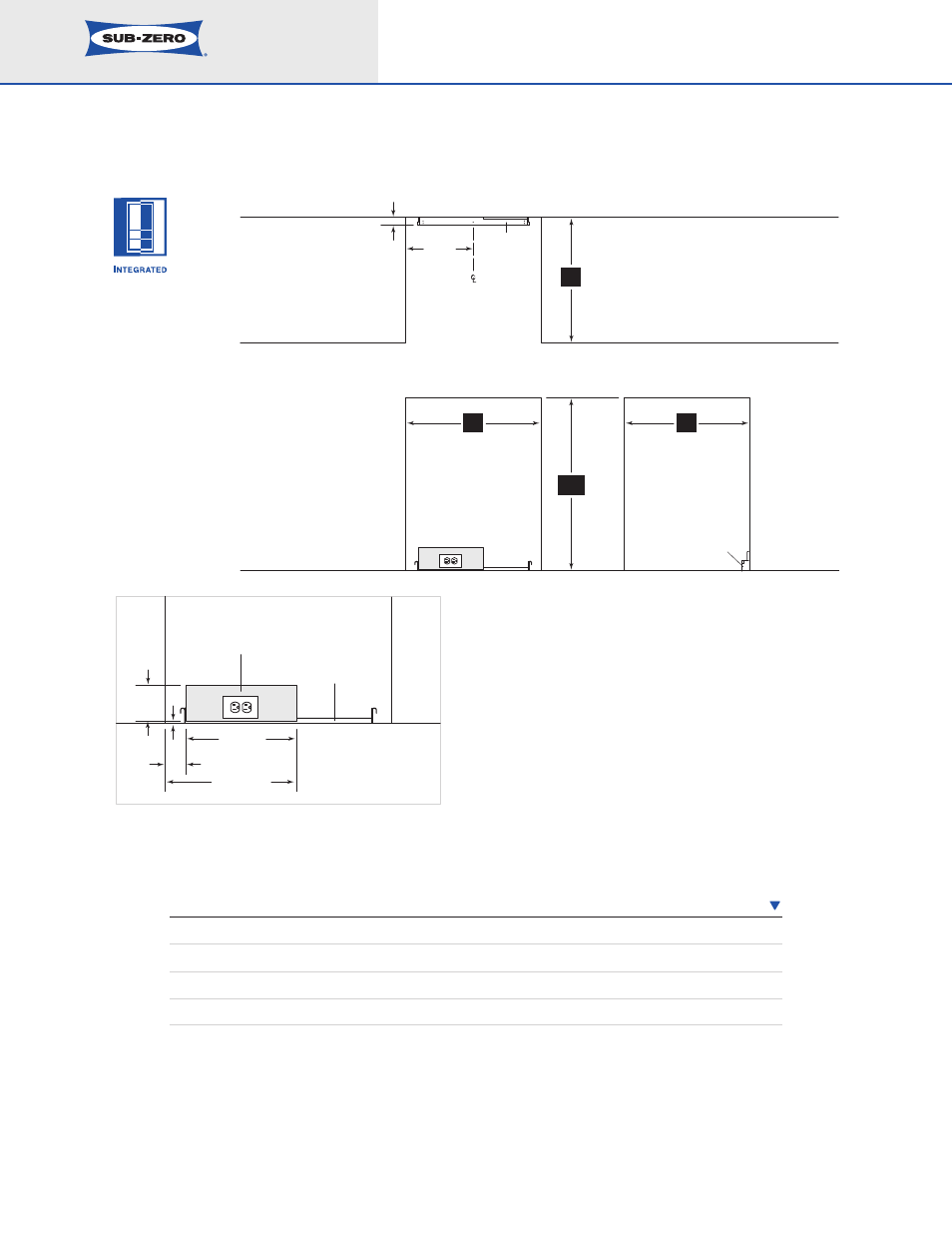
ANTI-TIP
BRACKET*
*PLACEMENT OF THE
ANTI-TIP BRACKET
SHOULD BE 24" (610)
FROM THE FRONT OF THE
UNIT WITHOUT PANELS
TO THE BACK OF THE
ANTI-TIP BRACKET.
4
1
/
2
"
(114)
2
1
/
2
"
(64)
15
1
/
2
"
(394)
1
/
4
"
(6)
13"
(330)
ANTI-TIP
BRACKET
LOCATE ELECTRICAL WITHIN
SHADED AREA – ORIENT GROUND
PRONG TO RIGHT AS SHOWN
25"
(635)
27"
(686)
34
1
/
2
"
(876)
25"
(635)
1
1
/
2
"
(38)
13
1
/
2
"
(343)
TOP VIEW
SIDE VIEW
FRONT VIEW
ANTI-TIP
BRACKET
NOTE: ANTI-TIP BRACKET MUST BE INSTALLED TO
PREVENT UNIT FROM TIPPING FORWARD
Planning Information
Integrated Model 700BR
Dimensions in parentheses are in
millimeters unless otherwise specified.
4
I N S T A L L A T I O N S P E C I F I C A T I O N S
D I M E N S I O N S
Finished Rough Opening Width
27" (686)
Finished Rough Opening Height
34
1
/
2
" (876)
Finished Rough Opening Depth
25" (635)*
Location of Electrical
Within shaded area
* The depth of the Model 700BR is 24" (610) from the front of the unit to its back. Your design
may necessitate moving the unit back, or cabinets forward to achieve a flush fit. This will require
a minimum rough opening depth of 25" (635).
See Installation Instructions shipped with unit for detailed specifications.