Chapter one connecting the set top box – Samsung SIR-T165 User Manual
Page 15
1.5
CHAPTER ONE
Connecting The Set Top Box
1
1
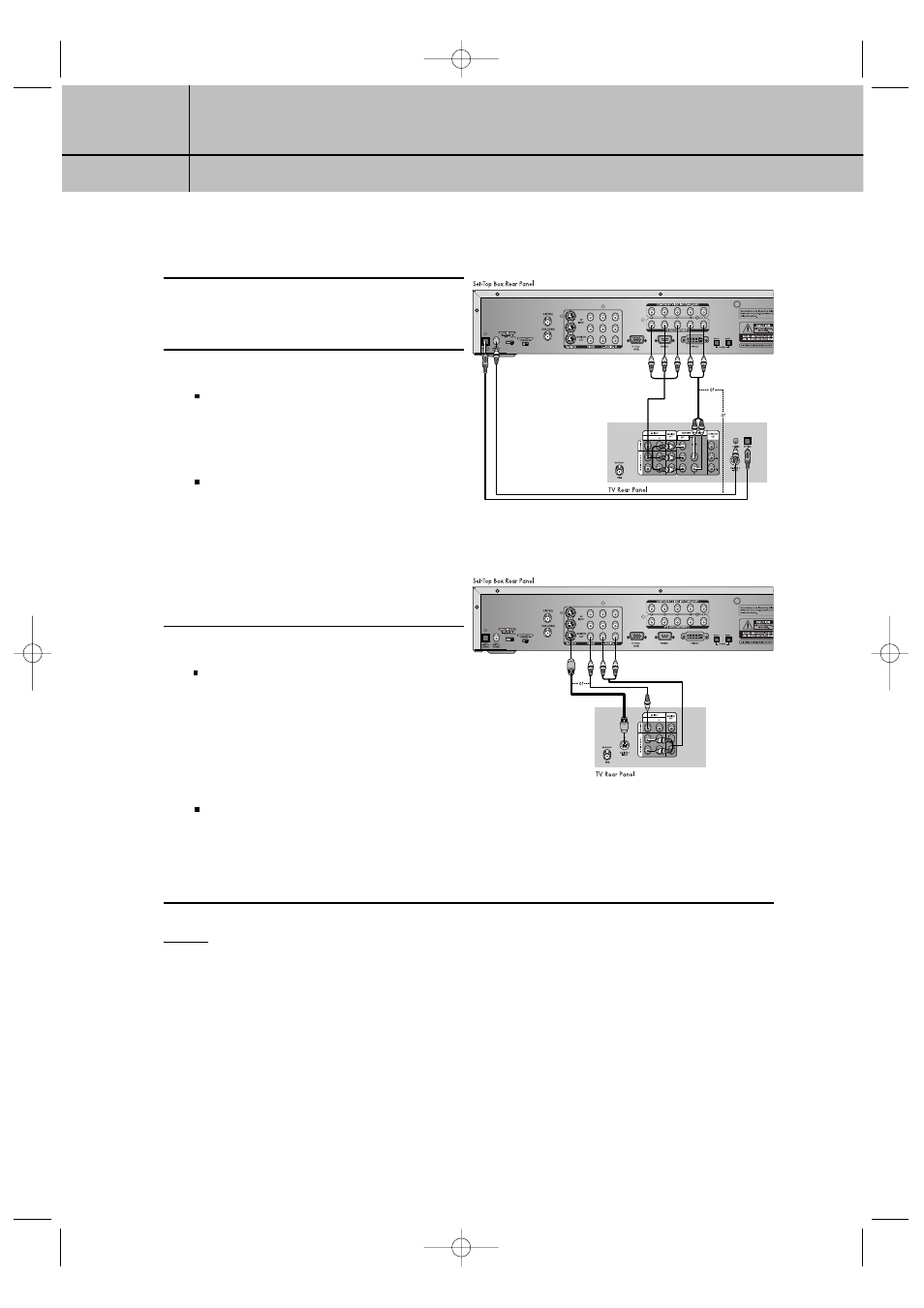
Digital Ready TV or Normal TV
1
Connect an antenna cable to the RF input
jacks on the SetTop Box.
2
Connect the Video Cables.
Digital Ready TV: Connect a video
cable between the DTV OUT COMPO-
NENT (YP
B
P
R
) jacks on the Set-Top Box and
the DTV INPUT jacks on the TV.
Normal TV: Connect a video cable
between the VIDEO OUT jack on the Set-
Top Box and the VIDEO INPUT jack on the
TV. Or, connect an S-Video cable between
the S-VIDEO OUTPUT jack on the Set-Top
Box and the S-VIDEO INPUT jack on the
TV.
3
Connect the Audio Cables
Digital Ready TV: Connect an audio
cable between the DOLBY DIGITAL OUT
(optical or coaxial) jack on the Set-Top Box
and the Dolby Digital In jack on the TV.
Or, connect an audio cable between the
Lt/Rt AUDIO OUT jacks on the Set-Top Box
and the L/R AUDIO IN jacks on the TV.
Normal TV: Connect an audio cable
between the L/R AUDIO OUT jacks on the
Set-Top Box and the L/R AUDIO IN jacks
on the TV.
NOTES
•
The TV set must be “digital compatible” (i.e., it must have appropriate audio and digital video
terminals).
•
If 1080i, 720p, or 480p (DIGITAL) is selected with the RESOLUTION SELECT switch on the Set-Top
Box, the On-Screen Display menus will not be supported for VIDEO OUT and S-VIDEO OUT. The
OSD menus for VIDEO OUT and S-VIDEO OUT are supported only when 480i (ANALOG) is
selected.
•
You must set “DTV OUT SELECT (YP
B
P
R
/RGB, DVI)” for YP
B
P
R
interface.
< Normal TV>
MD68-00278A(E)-CHAPTER 1 3/8/03 1:07 PM Page 5