Ab4 ethernet development board, Table 2. ab4 board signals, Ethernet-dk – Silicon Laboratories Network Card User Manual
Page 33
Ethernet-DK
Rev. 0.6
33
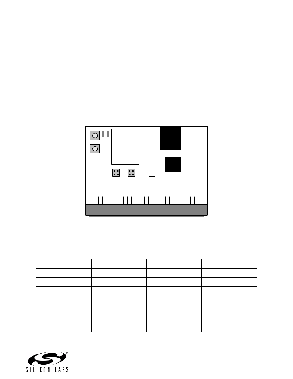
9. AB4 Ethernet Development Board
The Embedded Ethernet Development Kit includes the AB4 Ethernet Development Board designed to connect the
C8051F120 (or C8051F340, C8051F020, C8051F040, or C8051F060) target board to an ethernet network. The
ethernet controller used is the CP2200. Refer to Figure 29 for the locations of the various I/O connectors.
P1
96-pin Expansion I/O connector
U1
CP2200 Ethernet Controller
J1
RJ-45 Ethernet Connector
SW1, SW2
Input Switches
LED1, LED2
Output LEDs
J4
Disconnects SW2 from P1
J3
Disconnects SW1 from P1
J5
Disconnects LED1 from P1
J6
Disconnects LED2 from P1
Figure 29. AB4 Ethernet Development Board
The AB4 Ethernet development board is compatible with multiple MCU development boards that contain a 96-pin
connector. Table 2 maps select signals on the AB4 board to the corresponding MCU port pin(s).
Table 2. AB4 Board Signals
AB4 Signal Name
F020, F040, & F120
F060
F340
SW1
P2.0/P4.1
P2.0
P1.1
SW2
P2.1/P4.2
P2.1
P1.2
LED1
P2.2/P4.3
P2.2
P1.3
LED2
P2.3/P4.4
P2.3
P1.4
INT
P2.4/P0.3
P2.4/P0.3
P0.3
RST
P4.5
P4.5
P1.0
A15_CS
P5.7
P5.7
P2.7
RJ45
CP2200
AB4 Ethernet Development Board
LE
D1
LE
D2
SW
2
S
W1
J6
J5 J3
J4
Prototyping
Area