Sony ECM-3711 User Manual
Page 43
User’s Manual
ECM-3711 Series User’s Manual
43
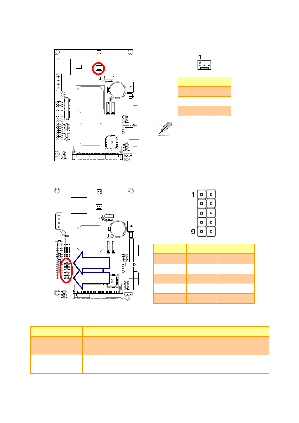
2.4.19
Single Power Select (JSUS1)
Signal
PIN
PWR_ON
1
+5V 2
VCCSB
3
Note:
The default sets 2-3 closed
for single power used.
2.4.20
USB Connector 0, 1, 2 & 3 (JUSB1, JUSB2)
Signal
PIN
PIN
Signal
+5V
1
2
GND
D1-/D3- 3 4 GND
D1+/D3+
5
6
D0+/D2+
GND 7
8 D0-/D2-
GND
9
10
+5V
2.4.20.1 Signal Description – USB Connector 0, 1, 2 & 3 Connector (JUSB1, JUSB2)
Signal
Signal Description
D0+/-, D2+/-
Differential bi-directional data signal for USB channel 0, 2. Clock is transmitted
along with the data using NRZI encoding. The signalling bit rate is up to 12 Mbs.
D1+/-, D3+/-
Differential bi-directional data signal for USB channel 1, 3. Clock is transmitted
along with the data using NRZI encoding. The signalling bit rate is up to 12 Mbs.
JUSB2
JUSB1
- SNC-RZ30P/2 (8 pages)
- VPCS1 (4 pages)
- Metz SCA 3302 M7 (160 pages)
- CD-R Drive Unit CDU948S (29 pages)
- SS2624 (91 pages)
- Ethernet Network Adapter (12 pages)
- 486DX (71 pages)
- MSA-4A (2 pages)
- VPCSB (4 pages)
- BKS-R3203 (158 pages)
- BKMW-E3000 (50 pages)
- CRX - 160E (13 pages)
- BKM-FW31 (100 pages)
- PCWA-A320 (65 pages)
- SU-WL100 (40 pages)
- DRX-510UL (2 pages)
- RHK40U2 (48 pages)
- AITi200STS (2 pages)
- CRX160E (2 pages)
- CRX-1611 (15 pages)
- AC-SQ950D (2 pages)
- CRX230A (2 pages)
- PCWA-A100 (28 pages)
- PCWA-A100 (17 pages)
- PCWA-A100 (61 pages)
- NAC-SV10I (92 pages)
- NAC-SV10I (11 pages)
- NAC-SV10I (2 pages)
- CLIE A-AVZ-100-11 (42 pages)
- PCLK-MN10A (113 pages)
- USM1GH (2 pages)
- USM1GH (2 pages)
- PCWA-C100 (48 pages)
- PCWA-C100 (68 pages)
- PCWA-C100 (1 page)
- PCWA-AR800 (2 pages)
- DRU-510A (2 pages)
- VPCEB Series Hard Disk Drive (Replacement Instructions) (3 pages)
- PCWA-A500 (32 pages)
- PCWA-A500 (61 pages)
- BKM-FW32 (100 pages)
- BKM-FW32 (1 page)
- PCNA-MR10 (132 pages)
- PCNA-MR10 (1 page)