Snapper 1691531 User Manual
Page 3
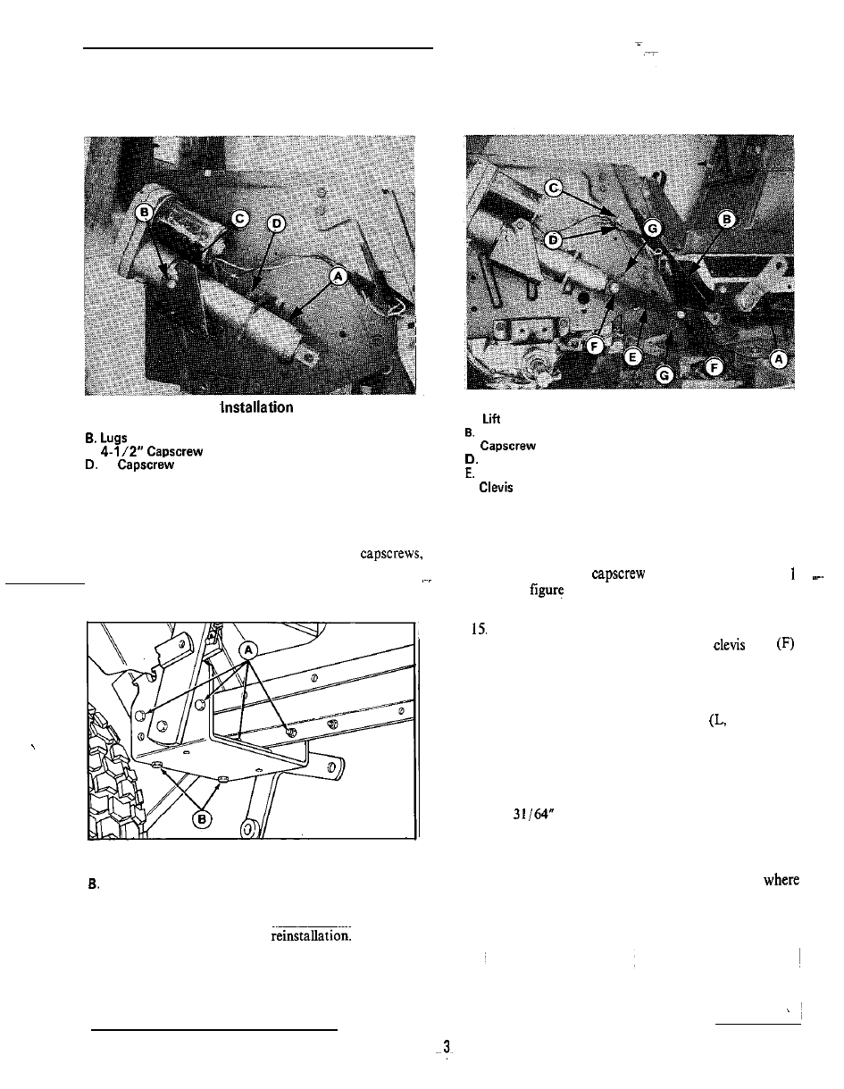
Figure 3. Cylinder
A. Cylinder
c.
1”
(from inside out)
12. Remove the manual lift lever as follows:
a. Remove the two capscrews and lockwashen (B,
figure 4). Leave the retaining nuts in place.
b. Remove the lever by removing four
lockwashers and nuts (A). Save the hardware for
reinstallation.
Figure 4. Manual Lift Lever
A. Capscrews, Lockwashers and Nuts
Capscrews and Lockwashers
c. Remove lift lever bracket support (B, figure 5).
Retain hardware for
13. Install new electric lift. lever bracket (A) reusing
existing hardware (mounted in same location).
Figure 5. Electric Lift Lever
A.
Lever Bracket
Bracket Support
c.
Wire Clip
Actuator Link
F.
Pin
G. Spring Clip
1 4 . Reinstall bracket support (B), reusing existing
hardware. In top
(C), install clip (F, figure
or D,
5). Clip and wiring are shown installed in
figure 5.
Mount actuator link (E) between cylinder and new
lift lever as shown in figure 5. Install
pins
from outside and spring clips (G) on inside. When
alignment is correct, tighten all mounting hardware.
NOTE
For rear-mounted attachments, lift rod
figure 1)
must be installed. Refer to last section of this
instruction sheet.
SWITCH INSTALLATION
16. A
hole must be drilled in the lower dash to
mount the switch (see figure 6). Measure two inches
down from upper dash and draw a line. Then,
measure three inches from right side of lower dash
and draw a vertical line. Drill the hole at point
these two lines meet (figure 6).