Assembly instructions – Stamina Products 55-1537C User Manual
Page 10
ASSEMBLY INSTRUCTIONS
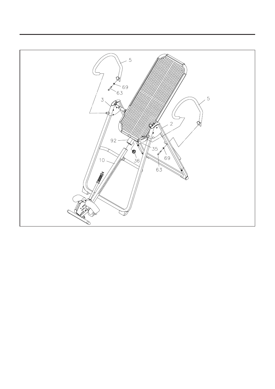
10
STEP 10
Install the
HEIGHT ADJUSTMENT BEAM(10)
into
MAIN FRAME(92)
by pulling the
SPRING PIN(35)
on the
MAIN FRAME(92)
and inserting the
HEIGHT ADJUSTMENT BEAM(10)
as shown. For added
safety, thread the
LOCKING KNOB
(3/8"-16 x 3/4")
(36)
into back side of the
MAIN FRAME(92).
WARNING:
Do not use the
Elite Inversion System
until you have verified your height setting. Failure
to use the proper height setting can result in difficulty recovering from the decline position.
See
HEIGHT ADJUSTMENT
instructions on page 11.
STEP 11
Insert the front ends of the
HANDRAILS(5)
onto the short tubes on
REAR FRAMES(2, 3).
Then attach
the back ends of the
HANDRAILS(5)
with
BOLTS(M8 x 50mm)(63)
and
WASHERS(M8)(69).