SATO CL612e User Manual
Page 10
CL ‘e’ Series Quick Guide
Pg 8
Other features can be enabled with different DSW switch combinations. The function
of each DSW switch is listed on a chart on the inside of the front cover. A more
detailed description is provided in the Operator & Technical Reference Manual,
Section 3. When changing configuration via the DSW switches, the power to the
printer must be cycled before the new settings become activated.
Computer Connections
The CL ‘e’ Series comes with Plug-In Interface card with the appropriate connector.
The type of Plug-In Interface card desired is specified at the time of order. It must be
installed in the printer before the computer connection is made.
To complete the installation, you will need the appropriate interface cable to connect
the printer to the output port of the host computer. These can be purchased locally or
from your SATO supplier. If you need additional information on interface types,
connector types or cabling pin-outs, please refer to Operator & Technical Reference
Manual, Section 6.
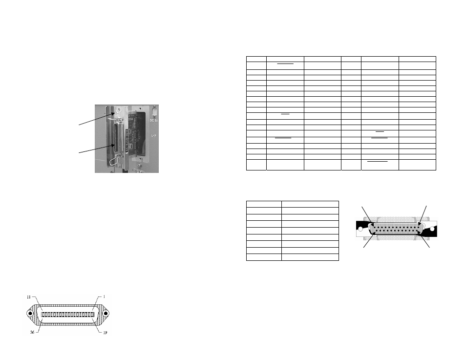
IEEE 1284 Parallel Interface
The Parallel interface connector is a female 36-pin Centronics type.
Centronics Connector On Printer
CL ‘e’ Series Quick Guide
Pg 9
PIN SIGNAL DIRECTION
PIN SIGNAL DIRECTION
1
STROBE
To Printer
19
STROBE Return
Reference
2
DATA 1
To Printer
20
DATA 1 Return
Reference
3
DATA 2
To Printer
21
DATA 2 Return
Reference
4
DATA 3
To Printer
22
DATA 3 Return
Reference
5
DATA 4
To Printer
23
DATA 4 Return
Reference
6
DATA 5
To Printer
24
DATA 5 Return
Reference
7
DATA 6
To Printer
25
DATA 6 Return
Reference
8
DATA 7
To Printer
26
DATA 7 Return
Reference
9
DATA 8
To Printer
27
DATA 8 Return
Reference
10
ACK
To Host
28
ACK Return
Reference
11 BUSY To
Host 29
Busy
Return
Reference
12
PTR ERROR
To Host
30
PE Return
Reference
13 SELECT To
Host 31 INIT
From Host
14
AUTOFD
(1)
To Host
32
FAULT
To Host
15
Not Used
33
Not Used
16 Logic
Gnd
34 Not
Used
17
FG
Frame Ground
35
Not Used
18
+5V
(Z=24K ohm)
To Host
36
SELECTIN
(1)
From
Host
(1)
Signals required for IEEE 1284 mode
Serial Interface
Pin No.
Description
1 Frame
Ground
2 Transmit
Data
3 Receive
Data
4 Request-To-Send
5 Clear-To-Send
6
Data Set Ready
7 Signal
Ground
20 Data
Terminal
Ready
The RS232 Serial Interface connector is a DB-25F. To correctly interface to a PC
serial port requires a DB-25P/9P to DB-25F Null Modem Cable. The DSW1
configuration settings for the RS232 data format must match those of the host system.
If they do not, the printer will beep when data is sent and display a FRAMING
ERROR message on the display. If the Baud Rate selected by DSW1-5 and DSW1-6
does not match that of the host, the printer will ignore any data sent. The serial baud
rate and word format settings can be changed on either the printer or the host to
correct the condition, but they must match.
Plug-In
Interface
Interface
Connector
Pin 25
Pin 13
Pin 1
Pin 14